Site preparation for DataScale SN30 rack installation
When preparing a site for rack installation, ensure that the requirements for physical space, power, cooling, networking, and cabling are met.
1. Physical specifications for each DataScale SN30 rack
The physical specifications in this section help you prepare the site for your DataScale SN30 rack.
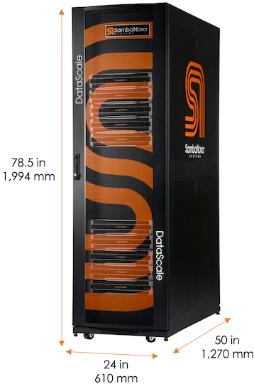
| Description | English | Metric |
|---|---|---|
Height |
78.5 in. |
1,994 mm |
Width |
24 in. |
610 mm |
Depth |
50 in. |
1,270 mm |
Packaged shipping height |
88.5 in. |
2,248 mm |
Packaged shipping width |
42 in. |
1,067 mm |
Packaged shipping depth |
64 in. |
1,626 mm |
| Description | English | Metric |
|---|---|---|
Minimum clearance cabinet top to overhead infrastructure |
24 in. |
610 mm |
Minimum clearance to front of rack for system installation and service |
32 in. |
812 mm |
Minimum clearance at rack rear for service |
24 in. |
610 mm |
| Configuration | Weight | Shipping Weight | ||
|---|---|---|---|---|
English |
Metric |
English |
Metric |
|
DataScale SN30 1 node |
738 lbs. |
335 kg |
1038 lbs. |
472 kg |
DataScale SN30 2 node |
1056 lbs. |
480 kg |
1356 lbs. |
616 kg |
2. Power requirements
Power requirements depend on the specific rack you are installing. Your SambaNova representative will discuss power draw, facility power requirements, and grounding requirements when you fill out your site-specific forms.
3. Network requirements
The DataScale SN30 rack requires that the customer provides, manages, and maintains certain networks. This section describes these networks and what is required from the customer.
3.1. Network architecture and layout
The following networks are used within the DataScale SN30 rack:
-
Data network
-
Management
-
Access network
Some customers combine the management and access network.
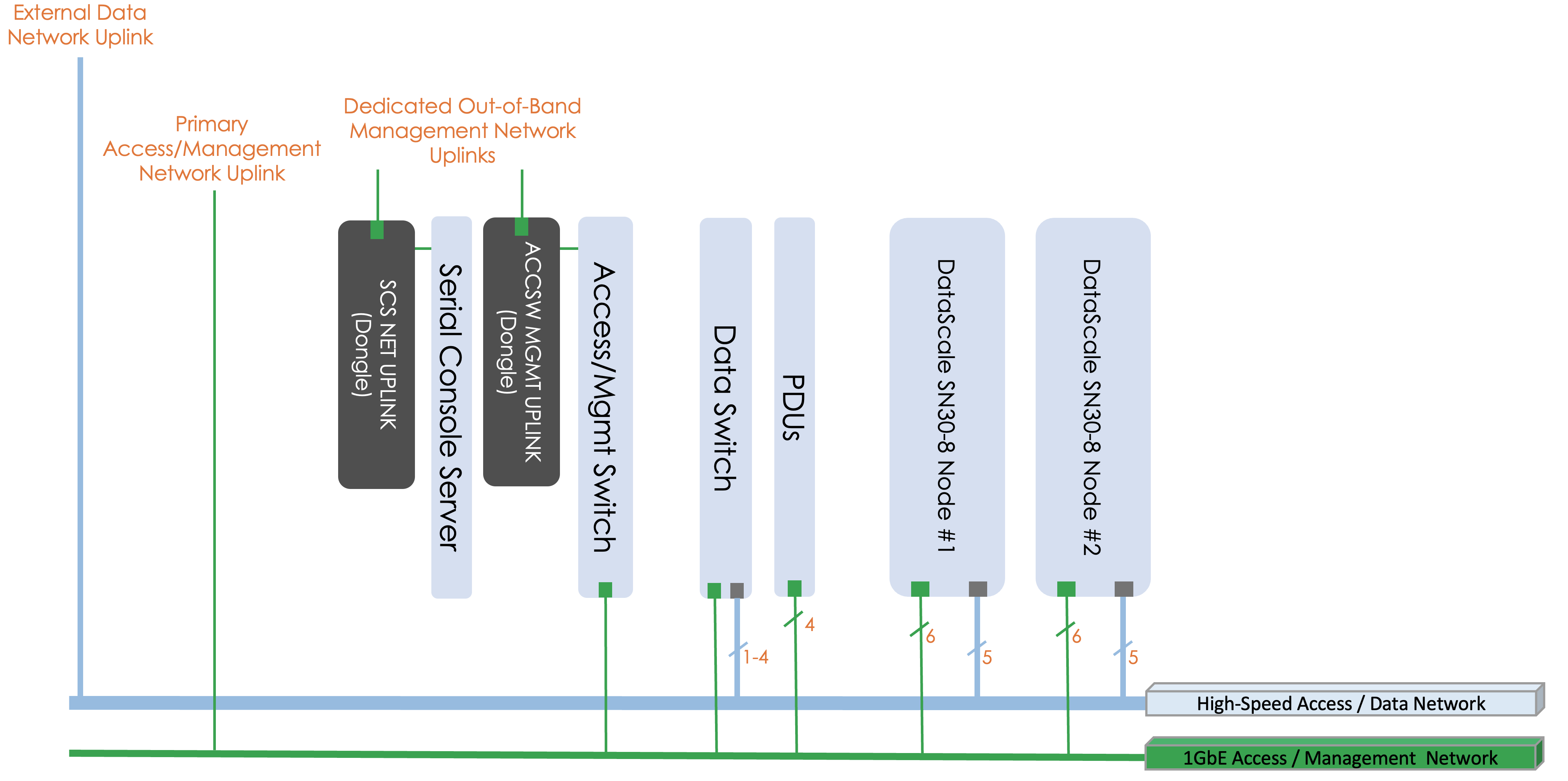
The data network is a high-bandwidth (200/400 GbE) Ethernet network used for the RDUs and SN30-H to take in data from an external source and for inter-RDU communication.
The management network is a 1GbE network used to log in to the DataScale SN30 rack components. This network connects to the baseboard management controller (BMC) of each component for power control, configuration, and monitoring/debugging, for other service operations. This network also connects to the SN30-H operating system to support day-to-day user operations on the systems, as discussed in the DataScale SN30 rack system administration document. Day-to-day operations might include streaming logs, performing software updates, and performing other system administration tasks.
Customers can choose to partition the access switch using port-based VLANs to separate access to the management interfaces of the DataScale SN30 rack components and the SN30-H OS interfaces. The customer is responsible for configuring this added network segregation. See Table 7. Access network port cabling in DataScale SN30 rack components and cabling for device to port mappings, and available ports that can be used if an additional network drop is required for the separate network. Alternatively, customers can leverage the high-bandwidth data network for user access to the systems.
These networks should typically be allocated a separate subnet to ensure the isolation of traffic, to regulate access to these networks.
3.2. Network infrastructure requirements
Ensure that network infrastructure is in place before starting installation.
Allocate a dedicated subnet and downlink for each network. To provide sufficient IP addressess for each of the networks, allocate:
-
A CIDR /26 subnet, or a subnet of 62 usable IP addresses, for the access network
-
A CIDR /27 subnet, or 30 usable IP addresses, for the data network.
The network architecture assumes that the first three IP addresses on each subnet are dedicated for redundant customer network infrastructure (for example, gateway VIP, switch failover IPs, and so on).
Provide three physical downlinks, two for the access network and one for the data network.
-
For the access network:
-
One downlink for the access network connects directly to the access switch.
-
The second downlink for the access network connects to the serial console server in the top of the DataScale SN30 rack. See Serial Console Server Cabling.
-
-
The downlink for the data network connects to the data switch.
The high-bandwidth switch might require that the customer configure multiple connections using a network aggregation (LACP/LAG) group to provide the necessary level of bandwidth to and from the rack. By default, only a single port is configured as an uplink. The following table gives details for each network.
| Network | Switch | Uplink Port | Port Type |
|---|---|---|---|
Data (/27) |
Juniper QFX5130 data Ethernet switch (default) |
31 4-port LAG of ports 27-30 |
QSFP-DD/QFSP-56 |
Access (/26) |
Juniper 1G access switch |
47 |
RJ45 |
Access (/26) |
Serial console server |
Dongle on left rear vertical bar of rack Labeled: SCS NET UPLINK |
RJ45 |
Access (/26) |
Access switch network management port |
Dongle on left rear vertical bar of rack Labeled: ACCSW MGMT UPLINK |
RJ45 |
|
To avoid spanning tree issues when initially connecting the rack to a customer network, do NOT plug in multiple uplinks from the data switch to the data network. Use only the single uplink on port 31 of the Juniper data switch initially. The default configuration of the switch has not been configured for the customer’s specific spanning tree configuration and multiple ports might lead to spanning tree issues. After local switch administrators have implemented proper local spanning tree configurations on the Juniper data switch, multiple uplinks can be used. |
4. Datacenter network requirements
Before the delivery of the DataScale SN30 rack, ensure that the datacenter network and power cabling have been prepared.
-
Route the required network outlets from the datacenter network infrastructure to where the DataScale SN30 rack will be installed.
-
Ensure that the setup tasks described in Network requirements have been completed.
| It is good practice to label the cables that are used to connect the two networks to the DataScale SN30 rack. |
5. Power cabling requirements
-
Route the necessary power drops to where the DataScale SN30 rack will be installed.
-
Ensure the power drops meet the power requirements, socket type, and socket quantity described in Power requirements.