Site preparation for Foundation Services Rack installation
When preparing a site for rack installation, ensure that the requirements for physical space, power, cooling, networking, and cabling are met.
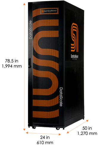
1. Physical specifications for the Foundation Services Rack
This section helps you prepare the site for your Foundation Services Rack installation.
| Description | English | Metric |
|---|---|---|
Height |
78.5 in. |
1,994 mm |
Width |
24 in. |
610 mm |
Depth |
50 in. |
1,270 mm |
Packaged shipping height |
88.5 in. |
2,248 mm |
Packaged shipping width |
42 in. |
1,067 mm |
Packaged shipping depth |
64 in. |
1,626 mm |
| Description | English | Metric |
|---|---|---|
Minimum clearance cabinet top to overhead infrastructure |
24 in. |
610 mm |
Minimum clearance to front of rack for system installation and service |
32 in. |
812 mm |
Minimum clearance at rack rear for service |
24 in. |
610 mm |
| Configuration | Weight | Shipping Weight | ||
|---|---|---|---|---|
English |
Metric |
English |
Metric |
|
Foundation Services Rack |
445 lbs. |
202 kg |
745 lbs. |
339 kg |
2. Power requirements
SambaNova representatives will discuss power draw, facility power requirements, and grounding requirements when you fill out your site-specific forms.
3. Network requirements
The Foundation Services Rack requires that the customer provides, manages, and maintains certain networks. This section describes these networks and what is required from the customer.
3.1. Network architecture and layout
The following networks are used within the Foundation Services Rack:
-
Data network
-
Management
-
Access network
These networks are distributed to the connected DataScale racks through the Foundation Services Rack as needed.
Some customers combine the management and access network.
The data network is a high-bandwidth (200/400 GbE) Ethernet network used for the RDUs and DataScale host systems to take in data from an external source and for inter-RDU communication. The data network between the Foundation Services Rack and each DataScale rack is via four 400GbE connections providing 1600GbE throughput between DataScale racks that are connected to the same Foundation Services Rack.
The management network is a 1GbE network used to log in to and administer the DataScale rack components. This network connects to the baseboard management controller (BMC) of each component for power control, configuration, and monitoring/debugging, and for other service operations. This network may also connect to the DataScale host’s operating system to support day-to-day user operations on the systems. Day-to-day operations might include streaming logs, performing software updates, and performing other system administration tasks.
Customers can choose to partition the access switch into access and management portions, using VLANs to separate access and management interfaces of the DataScale rack components from the DataScale host OS interfaces. In this scenario, the network used to connect to the OS interfaces is referred to as the access network. The customer is responsible for requesting and configuring this added network segregation when completing the site survey ahead of a deployment.
For details on the DataScale switch port mappings, see the DataScale components and cabling information in the installation guide for your SambaNova rack (SN40L, SN30, or SN10). For the Foundation Services Rack port mapping, see Foundation Services Rack components and cabling in this document.
If access and management networks are separated, they must be allocated on separate subnets. To ensure the isolation of traffic and to regulate access to these networks, separate VLANs are used to segregate the traffic on the access switch.
3.2. Network infrastructure requirements
Ensure that network infrastructure is in place before starting installation.
Allocate a dedicated subnet and downlink for each network. To provide sufficient IP addressess for each of the networks, allocate:
-
A CIDR /24 subnet for the management network as a minimum.
-
A CIDR /24 subnet for the access network as a minimum if separate from the management network.
-
A CIDR /24 subnet for the data network as a minimum.
The network architecture assumes that the first five IP addresses on each subnet are dedicated for redundant customer network infrastructure (for example, gateway VIP, switch failover IPs, and so on).
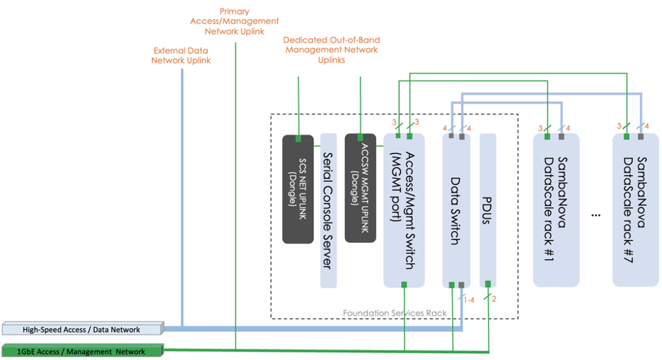
Provide additional download infrastructure. Provide at least four physical downlinks, three 1GbE links for the access/management network and at least one high-bandwidth fiber connection for the data network. You can provide as many as four high-bandwidth downlinks for the data network.
-
For the 1GbE access network:
-
One downlink is for the access network that connects directly to the access switch (trunk mode, VLAN tagging access and management networks).
-
The other two downlinks are for the access management network that connects to the serial console out-of-band management dongle and the access/mgmt switch out-of-band MGMT dongle (access mode, non-VLAN tagged).
-
-
The high-bandwidth downlinks for the data network connect to the data switch (trunk mode and configured for LACP/LAG if using multiple links).
Depending on customer bandwidth requirements, the high-bandwidth switch might require that the customer configure multiple connections using a network link aggregation group (LACP/LAG) to provide the necessary level of bandwidth to and from the rack. By default, a four port LAG uplink is provided from the Foundation Services Rack to the customer’s network. The following table gives details for each network.
| Network | Switch | Uplink port | Port type |
|---|---|---|---|
Data (/24) |
Juniper QFX5130 data Ethernet switch (default) |
4-port LAG of ports 27-30 |
QSFP-DD/QFSP-56/QSFP-28 |
Access (/24) |
Juniper 1G access switch |
47 (Trunk port VLAN tagging) |
RJ45 |
Access (/24) |
Serial console server |
Dongle on left rear vertical bar of rack Labeled: SCS NET UPLINK (Access port, non-tagged) |
RJ45 |
Access (/24) |
Access switch network management port |
Dongle on left rear vertical bar of rack Labeled: ACCSW MGMT UPLINK (Access port, non-tagged) |
RJ45 |
|
To avoid spanning tree issues when initially connecting the data switch to a customer network, ensure that the customer switch is properly configured for LAG/LACP. The default configuration of most switches does not provide suitable spanning-tree or multi-port LAG configurations and that might lead to spanning tree issues. After local switch administrators have implemented proper local spanning tree configurations on the Juniper data switch, multiple uplinks can be used. |
3.3. Datacenter network requirements
Before the delivery of the Foundation Services Rack and the DataScale rack, ensure that the datacenter network and power cabling have been prepared.
-
Route the required network outlets from the datacenter network infrastructure to where the Foundation Services Rack will be installed.
-
Ensure that the setup tasks described in Network requirements have been completed.
| It is good practice to label the cables that are used to connect the two networks to the Foundation Services Rack. |
4. Power cabling requirements
-
Route the necessary power drops to where the Foundation Services Rack and the DataScale racks will be installed.
-
Ensure the power drops meet the power requirements, socket type, and socket quantity discussed with your SambaNova representative.
-
Pay particular attention to the correct provisioning of data center redundant primary and backup power feeds to the PDUs in the Foundation Services Rack (FEED A and FEED B). The PDUs and power input cables will be appropriately labeled. A rack will continue to run, without interruption, if either FEED A or FEED B power is lost.
-
PDU power cables are 10ft (3m) long and are positioned towards the top of the rack. Ensure that datacenter power outlets are within reach of the PDU inlet cables.