Foundation Services Rack components and cabling
The Foundation Services Rack internal components are delivered preconfigured and cabled.
| You are not expected to interact with Foundation Services Rack or DataScale rack component unless explicitly instructed by this document or the SambaNova support team. |
You may be asked to interact with the cables for network and power components that have to be connected to the datacenter to provide power and connectivity to the Foundation Services Rack and connected DataScale racks.
-
Use port 47 of the access switch to connect an uplink to your network. See Access switch cabling.
-
The two dongles for the SCS (serial console server) and Access Switch management out-of-band access to your network. Dongles are located at the upper left rear of the rack.
-
Use port 28-31 of the high-bandwidth data switch to connect an uplink to your network. See High-bandwidth data switch cabling.
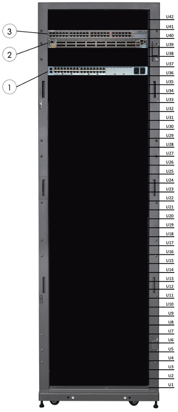
1. Foundation Services Rack components
The following image and table identify the locations of the main components in the Foundation Services Rack (rear facing).
| No. | Component Description |
|---|---|
1 |
Lantronix serial console server |
2 |
Juniper QFX5130 data switch (fan side) |
3 |
Juniper EX series access switch (fan side) |
2 x 0RU power distribution units (PDUs), not shown, are on the right and left sides of the rack when you face the rack rear. |
|
2. Serial console server cabling
The Latronix serial console server is installed and cabled in the factory.
| This section is for information only. Do not interact with these components unless instructed to do so by the SambaNova support team. |
This component, located in RU36, is positioned towards the front of the rack to allow its display and user interface buttons to be exposed when its vented blanking panel is removed for access. The serial console server uses standard Ethernet RJ45 cables for serial connectivity to RJ45 serial ports on connected devices.
A dedicated non-tagged VLAN network drop, which is on the management network, is required for the serial console server. This connection goes to a dongle on the left-rear side of the Foundation Services Rack labeled as SCS NET UPLINK (see Lantronix serial console server (rear view)). Having a dedicated serial console server network drop ensures that there is still network connectivity to the serial console server if recovery or reconfiguration of the Juniper EX series access switch is required.
| Ports for the serial console server are visible at the rear of the unit. These ports are not easily accessible from the rear of the rack due to the unit’s shallow depth. This component is primarily intended for SambaNova service and recovery operations. Customers are not expected to interact with the cabling. |
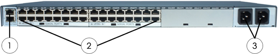
| No. | Component | Connector/cable type |
|---|---|---|
1 |
10/100/1000 management Network (labeled 1) |
RJ45, Cat6 or higher, brought out to a connector dongle labeled "SCS NET UPLINK" |
2 |
Serial RJ45 connections (ports 1–32) |
RJ45, Ethernet cable |
3 |
Two power inlets |
C13 to C14 power cord |
Cabling requirements from the Lantronix serial console server to the other Foundation Services Rack components are listed in the following table.
| From Serial Console Server Port | To Component | Component Location | Component Port |
|---|---|---|---|
1 |
Juniper EX series access switch |
RU40 |
CON |
2 |
Juniper QFX5130 Ethernet (default) high-bandwidth data switch |
RU39 |
CON |
3 |
(reserved for second/spare QFX5130 switch) |
(RU38) |
- |
4 |
PDU 1 |
Rear rack, right side, inner PDU |
RJ45 left of USB labeled 10101 |
5 |
PDU 2 |
Rear rack, right side, outer PDU |
RJ45 left of USB labeled 10101 |
6-9 |
- |
- |
- |
10 |
DataScale rack #1 SCS serial console |
- |
- |
11 |
DataScale rack #2 SCS serial console |
- |
- |
12 |
DataScale rack #3 SCS serial console |
- |
- |
13 |
DataScale rack #4 SCS serial console |
- |
- |
14 |
DataScale rack #5 SCS serial console |
- |
- |
15 |
DataScale rack #6 SCS serial console |
- |
- |
16 |
DataScale rack #7 SCS serial console |
- |
- |
17-32 |
- |
- |
- |
3. Access switch cabling
The Juniper EX series switch that is used for the access and management networks is installed and cabled in the factory. This switch is located in RU40 at the rear of the rack. Cables used for this switch are standard Cat6 Ethernet RJ45 cables.
Customers may request segregation of this switch using port-based VLANs to separate access to the management or access interfaces of the Foundation Services Rack and connected DataScale rack components. The customer is responsible to request this added network segregation and ensure properly VLAN tagged packets are provided to the switch uplink. Juniper EX series access switch components shows which device is connected to which port.
| If the switch is configured with separate the management and access interfaces based on port-based VLANs, and if the switch is later reset to factory default, the VLAN configuration is lost. This could result in lost communications and network spanning-tree issues. |
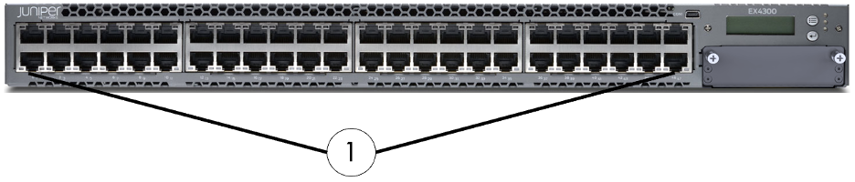
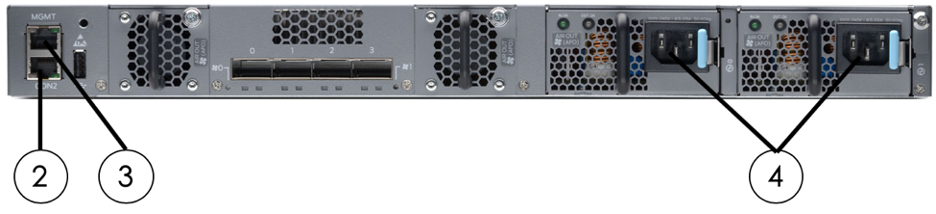
| No. | Component | Connector/Cable type |
|---|---|---|
1 |
1GbE ports (Ports 0–47) |
RJ45, Cat6 |
2 |
RJ45 serial console port |
RJ45, Cat6 |
3 |
Network management port for em0 |
RJ45, Cat6, brought out to a connection dongle labeled "ACCSW MGMT UPLINK" |
4 |
Two power inlets |
C13 to C14 power cord |
Cabling requirements from the Juniper EX series switch for the access network to the other DataScale racks are listed in the table below.
| From FS rack access switch port |
To component | Component location | Component port |
|---|---|---|---|
0-10 |
- |
- |
- |
11 |
DataScale rack #1 access switch uplink (Trunked, VLAN tagged) |
Right rear rack #1, RU42 |
port 47 |
12 |
DataScale rack #2 access switch uplink (Trunked, VLAN tagged) |
Right rear rack #2, RU42 |
port 47 |
13 |
DataScale rack #3 access switch uplink (Trunked, VLAN tagged) |
Right rear rack #3, RU42 |
port 47 |
14 |
DataScale rack #4 access switch uplink (Trunked, VLAN tagged) |
Right rear rack #4, RU42 |
port 47 |
15 |
DataScale rack #5 access switch uplink (Trunked, VLAN tagged) |
Right rear rack #5, RU42 |
port 47 |
16 |
DataScale rack #6 access switch uplink (Trunked, VLAN tagged) |
Right rear rack #6, RU42 |
port 47 |
17 |
DataScale rack #7 access switch uplink (Trunked, VLAN tagged) |
Right rear rack #7, RU42 |
port 47 |
18-20 |
- |
- |
- |
21 |
DataScale rack #1 SCS MGMT uplink dongle (Untagged, MGMT VLAN member) |
Left rear rack #1 |
SCS NET UPLINK dongle |
22 |
DataScale rack #2 SCS MGMT uplink dongle (Untagged, MGMT VLAN member) |
Left rear rack #2 |
SCS NET UPLINK dongle |
23 |
DataScale rack #3 SCS MGMT uplink dongle (Untagged, MGMT VLAN member) |
Left rear rack #3 |
SCS NET UPLINK dongle |
24 |
DataScale rack #4 SCS MGMT uplink dongle (Untagged, MGMT VLAN member) |
Left rear rack #4 |
SCS NET UPLINK dongle |
25 |
DataScale rack #5 SCS MGMT uplink dongle (Untagged, MGMT VLAN member) |
Left rear rack #5 |
SCS NET UPLINK dongle |
26 |
DataScale rack #6 SCS MGMT uplink dongle (Untagged, MGMT VLAN member) |
Left rear rack #6 |
SCS NET UPLINK dongle |
27 |
DataScale rack #7 SCS MGMT uplink dongle (Untagged, MGMT VLAN member) |
Left rear rack #7 |
SCS NET UPLINK dongle |
28-30 |
- |
- |
- |
31 |
DataScale rack #1 Access switch MGMT (Access, untagged, MGMT VLAN member) |
Left rear rack #1 |
ACCSW MGMT UPLINK dongle |
32 |
DataScale rack #2 Access switch MGMT (Access, untagged, MGMT VLAN member) |
Left rear rack #2 |
ACCSW MGMT UPLINK dongle |
33 |
DataScale rack #3 Access switch MGMT (Access, untagged, MGMT VLAN member) |
Left rear rack #3 |
ACCSW MGMT UPLINK dongle |
34 |
DataScale rack #4 Access switch MGMT (Access, untagged, MGMT VLAN member) |
Left rear rack #4 |
ACCSW MGMT UPLINK dongle |
35 |
DataScale rack #5 Access switch MGMT (Access, untagged, MGMT VLAN member) |
Left rear rack #5 |
ACCSW MGMT UPLINK dongle |
36 |
DataScale rack #6 Access switch MGMT (Access, untagged, MGMT VLAN member) |
Left rear rack #6 |
ACCSW MGMT UPLINK dongle |
37 |
DataScale rack #7 Access switch MGMT (Access, untagged, MGMT VLAN member) |
Left rear rack #7 |
ACCSW MGMT UPLINK dongle |
38-39 |
- |
- |
- |
40 |
PDU #1 |
Right rear, inner PDU |
01010 |
41 |
PDU #2 |
Right rear, outer PDU |
01010 |
42-43 |
- |
- |
- |
44 |
QFX5130 core switch #1 mgmt port (Access, untagged, Mgmt VLAN member) |
RU39 |
Mgmt net |
45-46 |
- |
- |
- |
47 |
Uplink to customer network (Trunked, tagged, Access & Mgmt VLAN member) |
RU39 |
Port 47 |
4. High-bandwidth data switch cabling
The Foundation Services Rack is configured with a Juniper QFX5130-32C 400Gb Ethernet switch.
| Customer may be requested to interact only with port 28-31 to connect an uplink to the customers network. The rest of this section is for information only. Do not interact with other components unless instructed to do so by the SambaNova support team. |
The Juniper QFX5130 switch, which is the standard high-bandwidth data switch in the Foundation Services Rack, is installed and cabled in the factory. This switch is located in RU39.
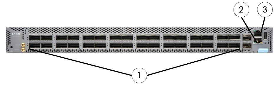
| No. | Component | Connector/Cable Type |
|---|---|---|
1 |
400GbE ports (ports 0-31) |
QSFP-DD |
2 |
Network management port |
RJ45, Cat6 |
3 |
RJ45 console port connection (CON) |
RJ45, Ethernet serial cable |
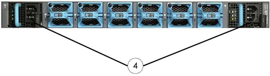
4 |
Two power inlets |
C13 to C14 power cord |
Cabling requirements for the high-bandwidth data network from the Juniper QFX5130 switch to the other DataScale racks, as well as the standard uplink ports, are listed in the following table:
| From FS rack Data switch port |
To DataScale component | Component location | Component port |
|---|---|---|---|
0-3 |
DataScale rack #1 Data switch uplink (Trunked, VLAN tagged) |
RU41 |
Rack #1, Data switch, ports 27-30 |
4-7 |
DataScale rack #2 Data switch uplink (Trunked, VLAN tagged) |
RU41 |
Rack #2, Data switch, ports 27-30 |
8-11 |
DataScale rack #3 Data switch uplink (Trunked, VLAN tagged) |
RU41 |
Rack #3, Data switch, ports 27-30 |
12-15 |
DataScale rack #4 Data switch uplink (Trunked, VLAN tagged) |
RU41 |
Rack #4, Data switch, ports 27-30 |
16-19 |
DataScale rack #5 Data switch uplink (Trunked, VLAN tagged) |
RU41 |
Rack #5, Data switch, ports 27-30 |
20-23 |
DataScale rack #6 Data switch uplink (Trunked, VLAN tagged) |
RU41 |
Rack #6, Data switch, ports 27-30 |
24-27 |
DataScale rack #7 Data switch uplink (Trunked, VLAN tagged) |
RU41 |
Rack #7, Data switch, ports 27-30 |
28-31 |
Uplink to customer network (Trunked, VLAN tagged) |
- |
- |
5. Power cabling of the Foundation Services Rack
Foundation Services Racks are delivered preinstalled with power cables from the factory.
| This section is for information only. Do not interact with these components unless instructed to do so by the SambaNova support team. |
Two power distribution units (PDUs) are installed in the Foundation Services Rack. The PDUs provide redundant power in case of a device PSU failure, a single PDU failure, or a datacenter power feed failure. They are located on the right side of the rack when you are facing the rear of the rack. The following table is a reference to the PDU identification and location within the rack.
| PDU Identification | Location in rack (facing rack rear) |
|---|---|
PDU1 |
Right side of rack, closest to the rack front/closest to the systems |
PDU2 |
Right side of rack, closest to the rack rear/furthest from the systems |
The PDU to component power supply mapping table shows all the required connections for a Foundation Services Rack.
| Do NOT use unused ports for any purpose. To prevent overloading of breaker circuits in the PDU and unexpected outages use only the designated ports. |
| From rack unit | From component | To PDU1 port | To PDU2 port |
|---|---|---|---|
40 |
Juniper EX series access switch PSU 1 (right PSU when facing rear of switch) |
1 |
- |
40 |
Juniper EX series access switch PSU 1 (left PSU when facing rear of switch) |
- |
1 |
39 |
Juniper QFX5130 data switch Eth PSU 1 (right PSU when facing rear of switch) |
3 |
- |
39 |
Juniper QFX5130 data switch Eth PSU 1 (left PSU when facing rear of switch) |
- |
3 |
36 |
Lantronix console server PSU2 (right PSU when facing rear of switch) |
2 |
- |
36 |
Lantronix console server PSU1 (left PSU when facing rear of switch |
- |
2 |