Site preparation for DataScale SN10-8R installation
Ensure that the following specifications are met regarding physical space, power, cooling, networking, and cabling when preparing a site for rack installation.
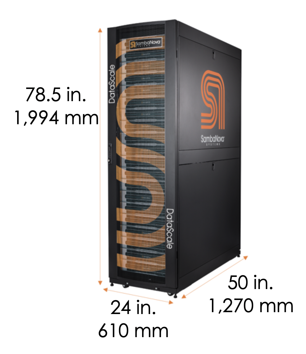
1. Physical specifications for each DataScale SN10-8R
| Description | English | Metric |
|---|---|---|
Height |
78.5 in. |
1,994 mm |
Width |
24 in. |
610 mm |
Depth |
50 in. |
1,270 mm |
Packaged shipping height |
88.5 in. |
2,248 mm |
Packaged shipping width |
42 in. |
1,067 mm |
Packaged shipping depth |
64 in. |
1,626 mm |
| Description | English | Metric |
|---|---|---|
Minimum clearance cabinet top to overhead infrastructure |
24 in. |
610 mm |
Minimum clearance to front of rack for system installation and service |
32 in. |
812 mm |
Minimum clearance at rack rear for service |
24 in. |
610 mm |
| Configuration | Weight | Shipping Weight | ||
|---|---|---|---|---|
English |
Metric |
English |
Metric |
|
DataScale SN10-8R Quarter Rack |
755 lbs. |
343 kg |
1055 lbs. |
480 kg |
DataScale SN10-8R |
1065 lbs. |
484 kg |
1365 lbs. |
620 kg |
DataScale SN10-8R |
1665 lbs. |
756 kg |
2025 lbs. |
919 kg |
2. Power requirements
Power requirements depend on the specific rack you are installing. Your SambaNova representative will discuss power draw, facility power requirements, and grounding requirements when you fill out your site-specific forms.
3. Network requirements
The DataScale SN10-8R requires certain networks to be provided as well as to be managed and maintained. This section describes these networks and what is required from the customer.
3.1. Network architecture and layout
There are three general networks that are used within the DataScale SN10-8R:
-
Data network
-
Management
-
Access network
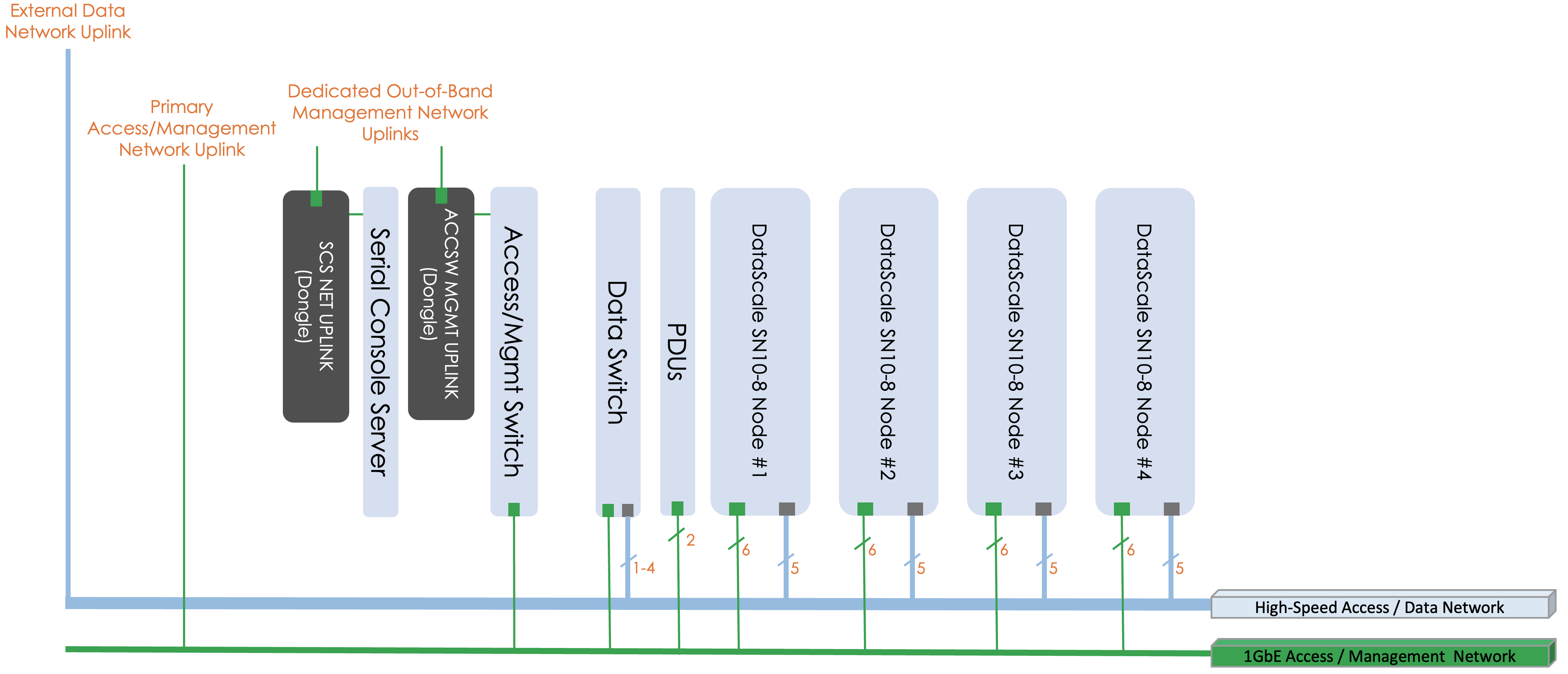
The data network is a high-bandwidth (100GbE) Ethernet network used for the RDUs and SN10-H to take in data from an external storage source and for inter-RDU communication.
The management network is a 1GbE network used to log in to the DataScale SN10-8R components. This network connects to each component’s baseboard management controller (BMC) for power control, configuration, and monitoring/debugging, as well to perform any other service operations. This network also connects to the systems’ SN10-H operating system (OS) to perform day-to-day user operations on the systems. This could include such operations as streaming logs, performing software updates, and performing other day-to-day system administration tasks.
Customers may choose to partition the access switch using port-based VLANs to separate access to the management interfaces of the DataScale SN10-8R components and the SN10-H OS interfaces. The customer is responsible for configuring this added network segregation. See DataScale SN10 2PDU rack components and cabling for background information. Alternatively, customers may leverage the high-bandwidth data network for user access to the systems as well.
These networks should typically be allocated a separate subnet to ensure the isolation of traffic, to regulate access to these networks.
3.2. Network infrastructure requirements
A dedicated subnet and downlink should be allocated for each of the networks described in xref:. A CIDR /26 subnet, or a subnet of 62 usable IP addresses, for the access network and a CIDR /27 subnet, or 30 usable IP addresses, for the data network provide sufficient IP addresses for each of the networks. There is an assumption that the first three IP addresses on each subnet will be dedicated for redundant customer network infrastructure (for example, gateway VIP, switch failover IPs, and so on).
In addition to the creation of these two subnets, three physical downlinks, two for the access network, and one for the data network need to be provided.
-
One downlink for the access network connects directly to the access switch.
-
The second downlink for the access network connects to the serial console server in the top of the DataScale SN10-8R as described in Serial console server cabling.
-
The downlink for the data network connects to the data switch.
The high-bandwidth switch may require that the customer configure multiple connections using a network aggregation (LACP/LAG) group in order to provide the necessary level of bandwidth to and from the rack. By default, only a single port is configured as an uplink. Details for each of these networks are described in the table below.
| Network | Switch | Uplink Port | Port Type |
|---|---|---|---|
Data (/27) |
Juniper QFX5200 data Ethernet switch (default) |
31 |
QSFP28 |
Access (/26) |
Juniper 1G access switch |
47 |
RJ45 |
Access (/26) |
Serial console server |
Dongle on left rear vertical bar of rack |
RJ45 |
|
To avoid potential spanning tree issues when initially connecting the rack to a customer network, do NOT plug in multiple uplinks from the data switch to the data network. Only the single uplink on port 31 of the Juniper data switch should be used initially. The default configuration of the switch has not been configured for the customer’s specific spanning tree configuration and multiple ports may lead to spanning tree issues. Once local switch administrators have implemented proper local spanning tree configurations on the Juniper data switch, multiple uplinks can be used. |