DataScale SN10 2PDU rack components and cabling
The DataScale SN10-8R internal components are delivered pre-configured and cabled in the 42RU rack. This section is for informational purposes only and to help identify what is cabled internally. Customers are not expected to interact with the internal cabling of the DataScale SN10-8R rack.
1. Cables for customer interaction
The only cables that customers are expected to interact with are for network and power components that need to be connected to the datacenter to provide power and connectivity to the DataScale SN10-8R.
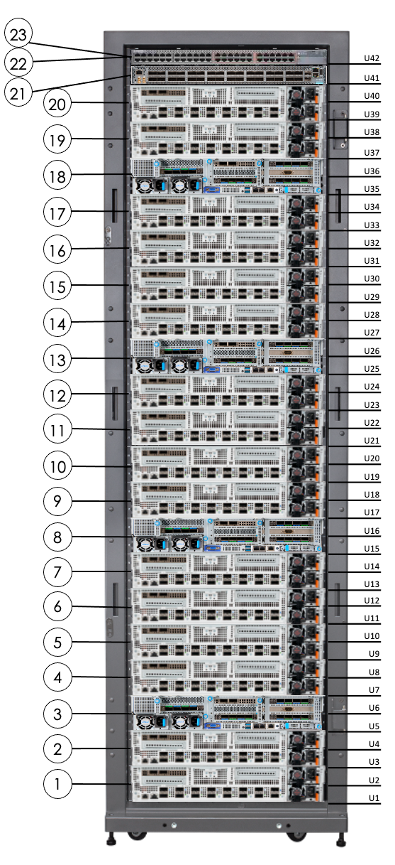
Figure 1 and Table 1 below identify the locations of the main components in the DataScale SN10-8R (rear facing).
| No. | Component Description |
|---|---|
1 |
SN10-H-1-XRDU0 (system 1) |
2 |
SN10-H-1-XRDU1 (system 1) |
3 |
SN10-H-1 (system 1) |
4 |
SN10-H-1-XRDU2 (system 1) |
5 |
SN10-H-1-XRDU3 (system 1) |
6 |
SN10-H-2-XRDU0 (system 2) |
7 |
SN10-H-2-XRDU1 (system 2) |
8 |
SN10-H-2 (system 2) |
9 |
SN10-H-2-XRDU2 (system 2) |
10 |
SN10-H-2-XRDU3 (system 2) |
11 |
SN10-H-3-XRDU0 (system 3) |
12 |
SN10-H-3-XRDU1 (system 3) |
13 |
SN10-H 3 (system 3) |
14 |
SN10-H-3-XRDU2 (system 3) |
15 |
SN10-H-3-XRDU3 (system 3) |
16 |
SN10-H-4-XRDU0 (system 4) |
17 |
SN10-H-4-XRDU1 (system 4) |
18 |
SN10-H-4 (system 4) |
19 |
SN10-H-4-XRDU2 (system 4) |
20 |
SN10-H-4-XRDU3 (system 4) |
21 |
Juniper QFX5200-32c Ethernet (default) high-bandwidth data switch |
22 |
Juniper EX4300 access switch |
23 |
Lantronix serial console server |
0RU PDUs (not shown) are on the right side of the rack when facing the rack rear |
|
2. Cabling system components
The DataScale SN10-8R comes pre-configured and cabled with the purchased number of systems connected to the appropriate switches and switch ports.
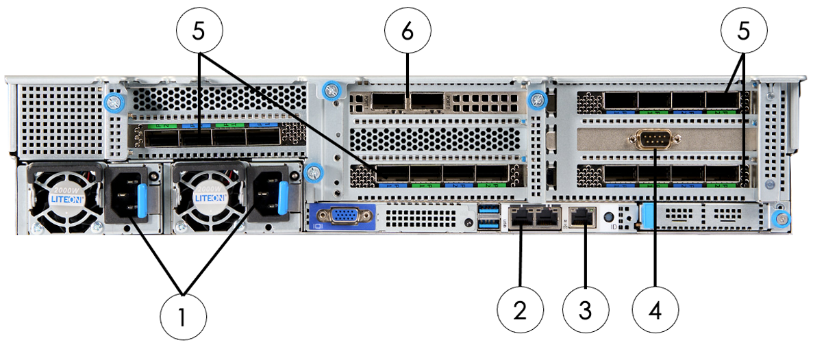
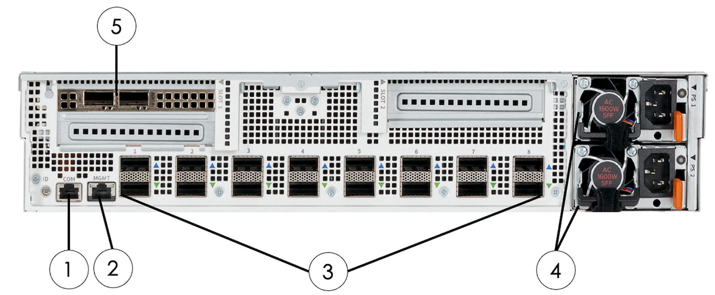
Figure 2, Figure 3, Table 2, and Table 3 below identify the components that will either be connected to switches or inter-connected to other system components.
| No. | Component | Connector/Cable Type |
|---|---|---|
1 |
Two power inlets |
C13 to C14 power cord |
2 |
SN10-H Net0 1GbE LAN |
RJ45, Cat5e or higher |
3 |
SN10-H 10/100/1000 management LAN (labeled “M”) |
RJ45, Cat5e or higher |
4 |
DB9 serial connection |
Rollover DB9F to RJ45 console cable |
5 |
Host interface card (HIC) |
QSFP-DD cable |
6 |
High-bandwidth network ports |
100GbE QSFP28 DAC cable |
| No. | Component | Connector/Cable Type |
|---|---|---|
1 |
SN10-2 COM serial port (COM) |
RJ45, Cat5e or higher |
2 |
SN10-2 10/100/1000 management LAN (MGMT) |
RJ45, Cat5e or higher |
3 |
Host HIC connections (8 pairs) |
QSFP-DD cable |
4 |
Two power inlets |
C13 to C14 power cord |
5 |
High-bandwidth network port connections |
100GbE QSFP28 DAC cable |
3. Serial console server cabling
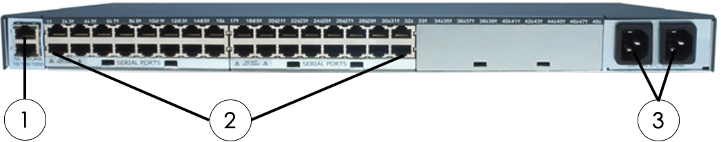
The serial console server is installed and cabled in the factory. This component is located in RU42, and it occupies the front portion of the same rack unit as the Juniper EX4300 access switch. Cables used for this are standard Ethernet RJ45 cables and rollover DB9F to RJ45 console cables for the DataScale SN10-H systems.
A dedicated non-tagged VLAN network drop, that is on the access/management network, is required for the serial console server. This connection goes to the serial console server management port indicated by the number 1 in Figure 4 below. This ensures there is still network connectivity to the serial console server if anything should happen to the Juniper EX4300 access switch.
| Please note that ports for this device are not visible or accessible to the user due to the physical location of the unit in front of the access switch. This device is primarily intended for SambaNova service operations. |
| No. | Component | Connector/Cable Type |
|---|---|---|
1 |
10/100/1000 management Network (labeled “1”) |
RJ45, Cat5e or higher |
2 |
Serial RJ45 connections (ports 1–32) |
RJ45, Ethernet cable |
3 |
Two power inlets |
C13 to C14 power cord |
Cabling requirements from the Lantronix serial console server to the other DataScale SN10-8 rack components are listed in Table 5 below.
| From Serial Console Server Port | To Component | Component Location | Component Port |
|---|---|---|---|
1 |
Juniper EX4300 |
RU42 |
CON2 |
2 |
Juniper QFX5200 Ethernet |
RU41 |
CON (Juniper) |
3 |
PDU 1 |
Right side of rack, closest to the rack front |
RJ45 just left of USB labeled “10101” |
4 |
PDU 2 |
Right side of rack, closest to the rack rear |
RJ45 just left of USB labeled “10101” |
5 |
- |
- |
- |
6 |
- |
- |
- |
7 |
SN10-H-4-XRDU3 |
RU39/RU40 |
COM |
8 |
SN10-H-4-XRDU2 |
RU37/RU18 |
COM |
9 |
SN10-H-4 |
RU35/RU36 |
DB9 male PCI card |
10 |
SN10-H-4-XRDU1 |
RU33/RU34 |
COM |
11 |
SN10-H-4-XRDU0 |
RU31/RU32 |
COM |
12 |
SN10-H-3-XRDU3 |
RU29/RU30 |
COM |
13 |
SN10-H-3-XRDU2 |
RU27/RU28 |
COM |
14 |
SN10-H-3 |
RU25/RU26 |
DB9 male PCI card |
15 |
SN10-H-3-XRDU1 |
RU23/RU24 |
COM |
16 |
SN10-H-3-XRDU0 |
RU21/RU22 |
COM |
17 |
SN10-H-2-XRDU3 |
RU19/RU20 |
COM |
18 |
SN10-H-2-XRDU2 |
RU17/RU18 |
COM |
19 |
SN10-H-2 |
RU15/RU16 |
DB9 male PCI card |
20 |
SN10-H-2-XRDU1 |
RU13/RU14 |
COM |
21 |
SN10-H-2-XRDU0 |
RU11/RU12 |
COM |
22 |
SN10-H-1-XRDU3 |
RU9/RU10 |
COM |
23 |
SN10-H-1-XRDU2 |
RU7/RU8 |
COM |
24 |
SN10-H-1 |
RU5/RU6 |
DB9 male PCI card |
25 |
SN10-H-1-XRDU1 |
RU3/RU4 |
COM |
26 |
SN10-H-1-XRDU0 |
RU1/RU2 |
COM |
27-32 |
- |
- |
- |
4. Access switch cabling
The Juniper EX4300 switch used for the access networks is installed and cabled in the factory. This component is located in RU42 at the rear of the rack and is shared in the same rack unit as the Lantronix serial console server. Cables used for this are standard Cat6 Ethernet RJ45 cables. This switch can further be segregated using port-based VLANs to separate access to the management interfaces of the DataScale SN10-8R components and the SN10-Hs’ operating system(OS) interface. The customer is responsible to configure this added network segregation. Please refer to Table 7 for what device is connected to which port, and available ports that can be used if an additional network drop is required for the separate network. This port separation can be configured by SambaNova if requested during initial deployment.
| Warning: When configuring the access switch to separate the management interfaces and the SN10-H OS interfaces with port-based VLANs, a separate network drop must be used for each network. Be aware that if the switch is reset to factory default for whatever reason, the VLAN configuration is lost. This could result in spanning-tree protocols disabling one or both of the networks. By default, the access switch is configured for Rapid Spanning Tree Protocol (RSTP). |
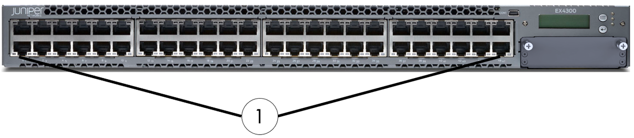
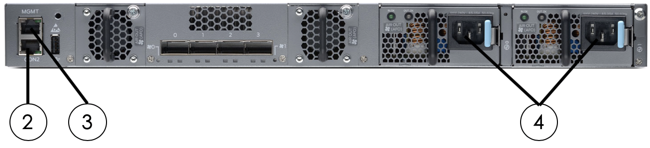
| No. | Component | Connector/Cable Type |
|---|---|---|
1 |
1GbE ports (Ports 0–47) |
RJ45, Cat5e or higher |
2 |
RJ45 console port |
RJ45, Cat5e or higher |
3 |
Network management port for em0 |
RJ45, Cat5e or higher |
4 |
Two power inlets |
C13 to C14 power cord |
Cabling requirements from the Juniper EX4300 switch for the access network to the other DataScale SN10-8 rack components are listed in Table 7.
| From Access Switch Port |
To Component | Component Location | Component Port |
|---|---|---|---|
0 |
- |
- |
- |
1 |
Juniper EX4300 access switch |
RU42 |
MGMT |
2 |
Juniper QFX5200-32c Ethernet |
RU41 |
C0 |
3 |
SN10-H-1-XRDU0 (system 1) |
RU1/RU2 |
MGMT |
4 |
SN10-H-1-XRDU1 (system 1) |
RU3/RU4 |
MGMT |
5 |
SN10-H-1-XRDU2 (system 1) |
RU7/RU8 |
MGMT |
6 |
SN10-H-1-XRDU3 (system 1) |
RU9/RU10 |
MGMT |
7 |
SN10-H-2-XRDU0 (system 2) |
RU11/RU12 |
MGMT |
8 |
SN10-H-2-XRDU1 (system 2) |
RU13/RU14 |
MGMT |
9 |
SN10-H-2-XRDU2 (system 2) |
RU17/RU18 |
MGMT |
10 |
SN10-H-2-XRDU3 (system 2) |
RU19/RU20 |
MGMT |
11 |
SN10-H-3-XRDU0 (system 3) |
RU21/RU22 |
MGMT |
12 |
SN10-H-3-XRDU1 (system 3) |
RU23/RU24 |
MGMT |
13 |
SN10-H-3-XRDU2 (system 3) |
RU27/RU28 |
MGMT |
14 |
SN10-H-3-XRDU3 (system 3) |
RU29/RU30 |
MGMT |
15 |
SN10-H-4-XRDU0 (system 4) |
RU31/RU32 |
MGMT |
16 |
SN10-H-4-XRDU1 (system 4) |
RU33/RU34 |
MGMT |
17 |
SN10-H-4-XRDU2 (system 4) |
RU37/RU38 |
MGMT |
18 |
SN10-H-4-XRDU3 (system 4) |
RU39/RU40 |
MGMT |
19-26 |
- |
- |
- |
27 |
PDU 1 |
Right side of rack, closest to the rack front |
RJ45 labeled |
28 |
PDU 2 |
Right side of rack, closest to the rack rear |
RJ45 Labeled |
29 |
- |
- |
- |
30 |
SN10-H-1 |
RU5/RU6 |
Labeled “M” |
31 |
SN10-H-2 |
RU15/RU16 |
Labeled “M” |
32 |
SN10-H-3 |
RU25/RU26 |
Labeled “M” |
33 |
SN10-H-4 |
RU35/RU36 |
Labeled “M” |
34-39 |
- |
- |
- |
40 |
Management Network Uplink |
- |
- |
41 |
Access Network Uplink |
- |
- |
42 |
- |
- |
- |
43 |
SN10-H-1 |
RU5/RU6 |
Left port Net0 |
44 |
SN10-H-2 |
RU15/RU16 |
Left port Net0 |
45 |
SN10-H-3 |
RU25/RU26 |
Left port Net0 |
46 |
SN10-H-4 |
RU35/RU36 |
Left port Net0 |
47 |
Access and Management Network Uplink |
- |
- |
5. High-bandwidth data switch cabling
The DataScale SN10-8R is configured with the Juniper QFX5200-32C 100GbE Ethernet switch.
5.1. High-bandwidth Ethernet switch
The Juniper QFX5200-32C switch, which is the standard high-bandwidth data switch in the DataScale SN10-8R, is installed and cabled in the factory. This switch is located in RU41.
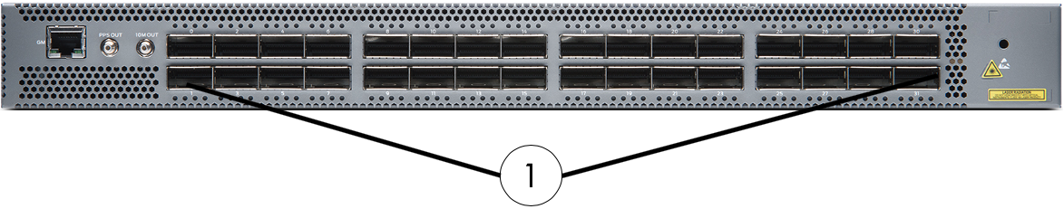
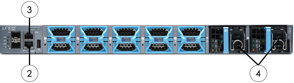
| No. | Component | Connector/Cable Type |
|---|---|---|
1 |
100GbE ports (ports 0–31) |
QSFP28 (or compatible) |
2 |
Network management port for em0 |
RJ45, Cat5e or higher |
3 |
RJ45 console port connection (CON) |
RJ45, Ethernet serial cable |
4 |
Two power inlets |
C13 to C14 power cord |
5.2. SN10-H and SN10-2 high-bandwidth network cabling
The high-bandwidth cabling for the SN10-Hs and SN10-2 systems is installed in the factory before delivery. The cabling used for this is high-bandwidth TwinAx cables.
Cabling requirements from the Juniper QFX5200-32c Ethernet switch for the high-bandwidth data network to the other DataScale SN10-8R components are listed in the table below.
| From Data Network Switch Port | To Component | Component Location | Component Port |
|---|---|---|---|
0 |
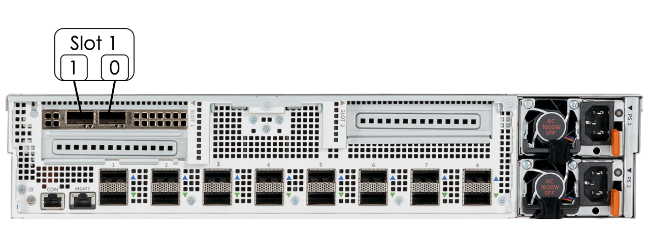
SN10-H-1-XRDU0 (system 1) |
RU1/RU2 |
PCIe slot 1 - Port 0 |
1 |
SN10-H-1-XRDU1 (system 1) |
RU3/RU4 |
PCIe slot 1 - Port 0 |
2 |
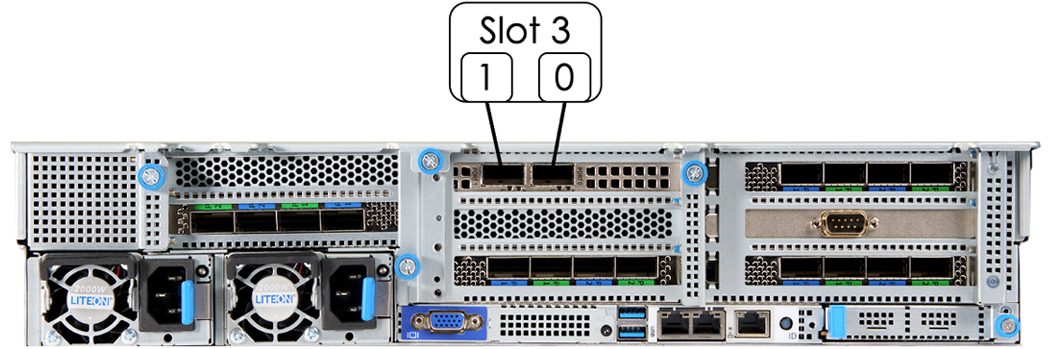
SN10-H-1 (system 1) |
RU5/RU6 |
PCIe slot 3 - Port 0 |
3 |
SN10-H-1-XRDU2 (system 1) |
RU7/RU8 |
PCIe slot 1 - Port 0 |
4 |
SN10-H-1-XRDU3 (system 1) |
RU9/RU10 |
PCIe slot 1 - Port 0 |
5 |
SN10-H-2-XRDU0 (system 2) |
RU11/RU12 |
PCIe slot 1 - Port 0 |
6 |
SN10-H-2-XRDU1 (system 2) |
RU13/RU14 |
PCIe slot 1 - Port 0 |
7 |
SN10-H-2 (system 1) |
RU15/RU16 |
PCIe slot 3 - Port 0 |
8 |
SN10-H-2-XRDU2 (system 2) |
RU17/RU18 |
PCIe slot 1 - Port 0 |
9 |
SN10-H-1-XRDU3 (system 2) |
RU19/RU20 |
PCIe slot 1 - Port 0 |
10 |
SN10-H-3-XRDU0 (system 3) |
RU21/RU23 |
PCIe slot 1 - Port 0 |
11 |
SN10-H-3-XRDU1 (system 3) |
RU23/RU24 |
PCIe slot 1 - Port 0 |
12 |
SN10-H-3 (system 3) |
RU25/RU26 |
PCIe slot 3 - Port 0 |
13 |
SN10-H-3-XRDU2 (system 3) |
RU27/RU28 |
PCIe slot 1 - Port 0 |
14 |
SN10-H-3-XRDU3 (system 3) |
RU29/RU30 |
PCIe slot 1 - Port 0 |
15 |
SN10-H-4-XRDU0 (system 4) |
RU31/RU32 |
PCIe slot 1 - Port 0 |
16 |
SN10-H-4-XRDU1 (system 1) |
RU33/RU34 |
PCIe slot 1 - Port 0 |
17 |
SN10-H-4 (system 1) |
RU35/RU36 |
PCIe slot 3 - Port 0 |
18 |
SN10-H-4-XRDU2 (system 4) |
RU37/RU38 |
PCIe slot 1 - Port 0 |
19 |
SN10-H-4-XRDU3 (system 4) |
RU39/RU40 |
PCIe slot 1 - Port 0 |
27–30 |
LAG uplinks to customer data network |
- |
- |
31 |
Non-LAG uplink to customer data network |
- |
- |
6. Intra-system SN10-2 and SN10-H cabling
Intra-system cabling is installed in the factory before delivery. These cables are not intended to be user serviceable. Intra-system SN10-H-to-SN10-2 and SN10-2-to-SN10-2 cables are specially designed QSFP-DD terminated cable pairs.
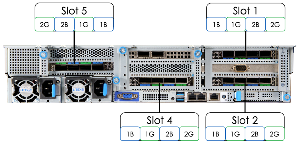
| Please note that the port numbering for a slot 5 cards is reversed. This is because the PCIe card orientation is different from the other cards. |
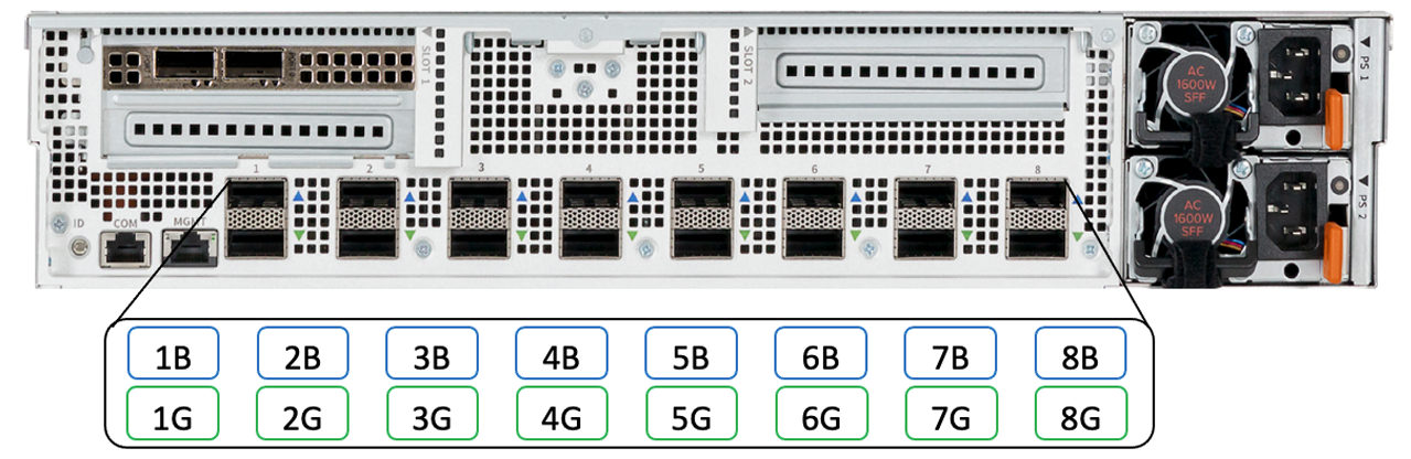
For cabling between the SN10-H server and the SN10-2 modules in a system, the ports are grouped with a blue and green pair. For example, the SN10-2 module’s port 1 consists of an upper blue port 1 and lower green port 1. This is highlighted in Figure 12.
For the SN10-H, there are two pairs of color-coded ports per PCIe card slot with only one of the pairs being used. For example, in slot 1 of an SN10-H, 1B and 1G are used for port pair 1 with 2B and 2G used for port pair 2, but for this particular card, only port pair 1 is used. This is shown in Figure 13.
In general, cabling between the SN10-H and the SN10-2s in a system looks as follows:
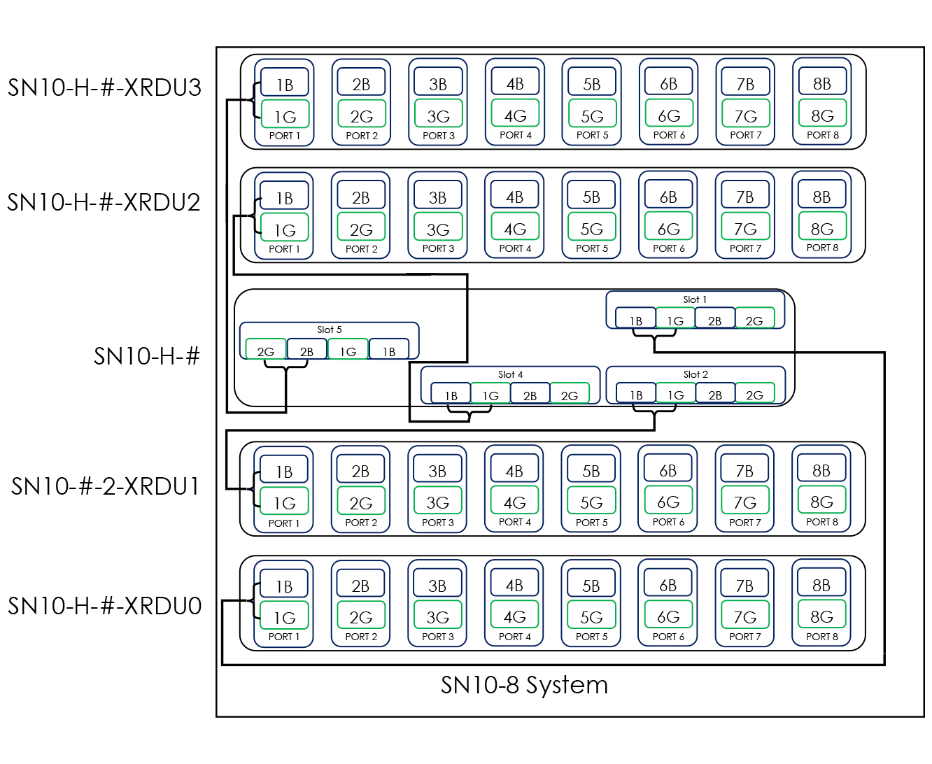
Where identified, the source blue port from the identified PCIe slot in the host goes to the corresponding target blue port 1 in the identified SN10-2s. Similarly, the source green port from the identified PCIe slot in the host goes to the corresponding target green port in the identified SN10-2. For example, from the host’s PCIe slot 1, slot 1 – Blue (1B) goes to the second SN10-2 in the node: Port 1 – Blue (1B). Each cable connection is detailed in Table 10 below. Also note that the plug ends on the cables are also color-coded green or blue.
| From SN10-H | Location | From SN10-H Card - Port | To SN10-2 | Location | To SN10-2 Port |
|---|---|---|---|---|---|
SN10-H-1 |
RU5/RU6 |
Slot 1-1B |
SN10-H-1-XRDU0 |
RU1/RU2 |
1B |
SN10-H-1 |
RU5/RU6 |
Slot 1-1G |
SN10-H-1-XRDU0 |
RU1/RU2 |
1G |
SN10-H-1 |
RU5/RU6 |
Slot 2-1B |
SN10-H-1-XRDU1 |
RU3/RU4 |
1B |
SN10-H-1 |
RU5/RU6 |
Slot 2-1G |
SN10-H-1-XRDU1 |
RU3/RU4 |
1G |
SN10-H-1 |
RU5/RU6 |
Slot 4-1B |
SN10-H-1-XRDU2 |
RU7/RU8 |
1B |
SN10-H-1 |
RU5/RU6 |
Slot 4-1G |
SN10-H-1-XRDU2 |
RU7/RU8 |
1G |
SN10-H-1 |
RU5/RU6 |
Slot 5-2B |
SN10-H-1-XRDU3 |
RU9/RU10 |
1B |
SN10-H-1 |
RU5/RU6 |
Slot 5-2G |
SN10-H-1-XRDU3 |
RU9/RU10 |
1G |
SN10-H-2 |
RU15/RU16 |
Slot 1-1B |
SN10-H-2-XRDU0 |
RU13/RU14 |
1B |
SN10-H-2 |
RU15/RU16 |
Slot 1-1G |
SN10-H-2-XRDU0 |
RU13/RU14 |
1G |
SN10-H-2 |
RU15/RU16 |
Slot 2-1B |
SN10-H-2-XRDU1 |
RU17/RU18 |
1B |
SN10-H-2 |
RU15/RU16 |
Slot 2-1G |
SN10-H-2-XRDU1 |
RU17/RU18 |
1G |
SN10-H-2 |
RU15/RU16 |
Slot 3-2B |
SN10-H-2-XRDU2 |
RU11/RU12 |
1B |
SN10-H-2 |
RU15/RU16 |
Slot 3-2G |
SN10-H-2-XRDU2 |
RU11/RU12 |
1G |
SN10-H-2 |
RU15/RU16 |
Slot 4-1B |
SN10-H-2-XRDU3 |
RU19/RU20 |
1B |
SN10-H-2 |
RU15/RU16 |
Slot 4-1G |
SN10-H-2-XRDU3 |
RU19/RU20 |
1G |
SN10-H-3 |
RU25/RU26 |
Slot 1-1B |
SN10-H-3-XRDU0 |
RU23/RU24 |
1B |
SN10-H-3 |
RU25/RU26 |
Slot 1-1G |
SN10-H-3-XRDU0 |
RU23/RU24 |
1G |
SN10-H-3 |
RU25/RU26 |
Slot 2-1B |
SN10-H-3-XRDU1 |
RU28/RU29 |
1B |
SN10-H-3 |
RU25/RU26 |
Slot 2-1G |
SN10-H-3-XRDU1 |
RU28/RU29 |
1G |
SN10-H-3 |
RU25/RU26 |
Slot 3-2B |
SN10-H-3-XRDU2 |
RU21/RU22 |
1B |
SN10-H-3 |
RU25/RU26 |
Slot 3-2G |
SN10-H-3-XRDU2 |
RU21/RU22 |
1G |
SN10-H-3 |
RU25/RU26 |
Slot 4-1B |
SN10-H-3-XRDU3 |
RU29/RU30 |
1B |
SN10-H-3 |
RU25/RU26 |
Slot 4-1G |
SN10-H-3-XRDU3 |
RU29/RU30 |
1G |
SN10-H-4 |
RU35/RU36 |
Slot 1-1B |
SN10-H-4-XRDU0 |
RU33/RU34 |
1B |
SN10-H-4 |
RU35/RU36 |
Slot 1-1G |
SN10-H-4-XRDU0 |
RU33/RU34 |
1G |
SN10-H-4 |
RU35/RU36 |
Slot 2-1B |
SN10-H-4-XRDU1 |
RU37/RU38 |
1B |
SN10-H-4 |
RU35/RU36 |
Slot 2-1G |
SN10-H-4-XRDU1 |
RU37/RU38 |
1G |
SN10-H-4 |
RU35/RU36 |
Slot 3-2B |
SN10-H-4-XRDU2 |
RU31/RU32 |
1B |
SN10-H-4 |
RU35/RU36 |
Slot 3-2G |
SN10-H-4-XRDU2 |
RU31/RU32 |
1G |
SN10-H-4 |
RU35/RU36 |
Slot 4-1B |
SN10-H-4-XRDU3 |
RU39/RU40 |
1B |
SN10-H-4 |
RU35/RU36 |
Slot 4-1G |
SN10-H-4-XRDU3 |
RU39/RU40 |
1G |
7. SN10-2 to SN10-2 Intra-system cabling
For the intra-system cabling between SN10-2 systems, the ports are grouped with a blue and green pair. For example, port 1 consists of blue port 1 above and green port 1 beneath. This is highlighted in Figure 14.
In general, the intra-system cabling of a SN10-2 system to other SN10-2 systems is done as follows:
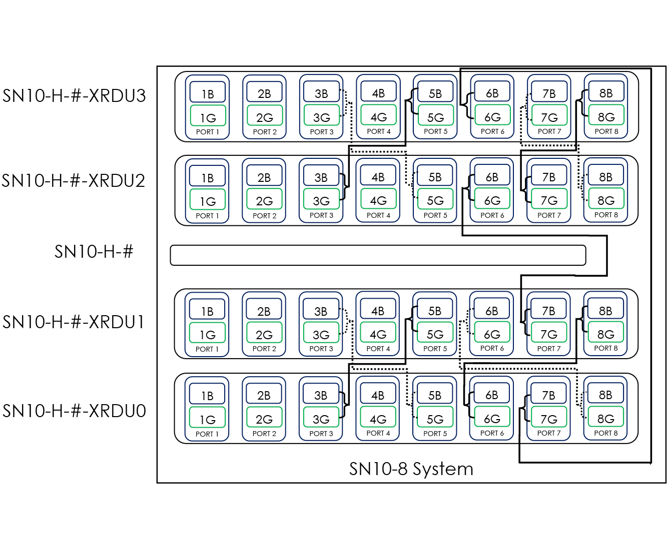
Where identified, the source blue port goes to the corresponding target blue port, and the source green port goes to the corresponding target green port. For example, from the first SN10-2 in a system, the Port 3 – Blue (3B) goes to the second SN10-2 in the system: Port 5 – Blue (5B). Each cable connection is detailed in the Table 11 below.
| From SN10-2 | Location | Port | To SN10-2 | Location | Port |
|---|---|---|---|---|---|
SN10-H-1-XRDU0 |
RU1/RU2 |
3B |
SN10-H-1-XRDU1 |
RU3/RU4 |
5B |
SN10-H-1-XRDU0 |
RU1/RU2 |
3G |
SN10-H-1-XRDU1 |
RU3/RU4 |
5G |
SN10-H-1-XRDU0 |
RU1/RU2 |
5B |
SN10-H-1-XRDU1 |
RU3/RU4 |
3B |
SN10-H-1-XRDU0 |
RU1/RU2 |
5G |
SN10-H-1-XRDU1 |
RU3/RU4 |
3G |
SN10-H-1-XRDU0 |
RU1/RU2 |
6B |
SN10-H-1-XRDU1 |
RU3/RU4 |
8B |
SN10-H-1-XRDU0 |
RU1/RU2 |
6G |
SN10-H-1-XRDU1 |
RU3/RU4 |
8G |
SN10-H-1-XRDU0 |
RU1/RU2 |
7B |
SN10-H-1-XRDU3 |
RU9/RU10 |
6B |
SN10-H-1-XRDU0 |
RU1/RU2 |
7G |
SN10-H-1-XRDU3 |
RU9/RU10 |
6G |
SN10-H-1-XRDU0 |
RU1/RU2 |
8B |
SN10-H-1-XRDU1 |
RU3/RU4 |
6B |
SN10-H-1-XRDU0 |
RU1/RU2 |
8G |
SN10-H-1-XRDU1 |
RU3/RU4 |
6G |
SN10-H-1-XRDU1 |
RU3/RU4 |
7B |
SN10-H-1-XRDU2 |
RU7/RU8 |
6B |
SN10-H-1-XRDU1 |
RU3/RU4 |
7G |
SN10-H-1-XRDU2 |
RU7/RU8 |
6G |
SN10-H-1-XRDU2 |
RU7/RU8 |
3B |
SN10-H-1-XRDU3 |
RU9/RU10 |
5B |
SN10-H-1-XRDU2 |
RU7/RU8 |
3G |
SN10-H-1-XRDU3 |
RU9/RU10 |
5G |
SN10-H-1-XRDU2 |
RU7/RU8 |
5B |
SN10-H-1-XRDU3 |
RU9/RU10 |
3B |
SN10-H-1-XRDU2 |
RU7/RU8 |
5G |
SN10-H-1-XRDU3 |
RU9/RU10 |
3G |
SN10-H-1-XRDU2 |
RU7/RU8 |
7B |
SN10-H-1-XRDU3 |
RU9/RU10 |
8B |
SN10-H-1-XRDU2 |
RU7/RU8 |
7G |
SN10-H-1-XRDU3 |
RU9/RU10 |
8G |
SN10-H-1-XRDU2 |
RU7/RU8 |
8B |
SN10-H-1-XRDU3 |
RU9/RU10 |
7B |
SN10-H-1-XRDU2 |
RU7/RU8 |
8G |
SN10-H-1-XRDU3 |
RU9/RU10 |
7G |
SN10-H-2-XRDU0 |
RU11/RU12 |
3B |
SN10-H-2-XRDU1 |
RU13/RU14 |
5B |
SN10-H-2-XRDU0 |
RU11/RU12 |
3G |
SN10-H-2-XRDU1 |
RU13/RU14 |
5G |
SN10-H-2-XRDU0 |
RU11/RU12 |
5B |
SN10-H-2-XRDU1 |
RU13/RU14 |
3B |
SN10-H-2-XRDU0 |
RU11/RU12 |
5G |
SN10-H-2-XRDU1 |
RU13/RU14 |
3G |
SN10-H-2-XRDU0 |
RU11/RU12 |
6B |
SN10-H-2-XRDU1 |
RU19/RU20 |
8B |
SN10-H-2-XRDU0 |
RU11/RU12 |
6G |
SN10-H-2-XRDU1 |
RU19/RU20 |
8G |
SN10-H-2-XRDU0 |
RU11/RU12 |
7B |
SN10-H-2-XRDU3 |
RU13/RU14 |
6B |
SN10-H-2-XRDU0 |
RU11/RU12 |
7G |
SN10-H-2-XRDU3 |
RU13/RU14 |
6G |
SN10-H-2-XRDU0 |
RU11/RU12 |
8B |
SN10-H-2-XRDU1 |
RU13/RU14 |
6B |
SN10-H-2-XRDU0 |
RU11/RU12 |
8G |
SN10-H-2-XRDU1 |
RU13/RU14 |
6G |
SN10-H-2-XRDU1 |
RU13/RU14 |
7B |
SN10-H-2-XRDU2 |
RU17/RU18 |
6B |
SN10-H-2-XRDU1 |
RU13/RU14 |
7G |
SN10-H-2-XRDU2 |
RU17/RU18 |
6G |
SN10-H-2-XRDU2 |
RU17/RU18 |
3B |
SN10-H-2-XRDU3 |
RU19/RU20 |
5B |
SN10-H-2-XRDU2 |
RU17/RU18 |
3G |
SN10-H-2-XRDU3 |
RU19/RU20 |
5G |
SN10-H-2-XRDU2 |
RU17/RU18 |
5B |
SN10-H-2-XRDU3 |
RU19/RU20 |
3B |
SN10-H-2-XRDU2 |
RU17/RU18 |
5G |
SN10-H-2-XRDU3 |
RU19/RU20 |
3G |
SN10-H-2-XRDU2 |
RU17/RU18 |
7B |
SN10-H-2-XRDU3 |
RU19/RU20 |
8B |
SN10-H-2-XRDU2 |
RU17/RU18 |
7G |
SN10-H-2-XRDU3 |
RU19/RU20 |
8G |
SN10-H-2-XRDU2 |
RU17/RU18 |
8B |
SN10-H-2-XRDU3 |
RU19/RU20 |
7B |
SN10-H-2-XRDU2 |
RU17/RU18 |
8G |
SN10-H-2-XRDU3 |
RU19/RU20 |
7G |
SN10-H-3-XRDU0 |
RU21/RU22 |
3B |
SN10-H-3-XRDU1 |
RU23/RU24 |
5B |
SN10-H-3-XRDU0 |
RU21/RU22 |
3G |
SN10-H-3-XRDU1 |
RU23/RU24 |
5G |
SN10-H-3-XRDU0 |
RU21/RU22 |
5B |
SN10-H-3-XRDU1 |
RU23/RU24 |
3B |
SN10-H-3-XRDU0 |
RU21/RU22 |
5G |
SN10-H-3-XRDU1 |
RU23/RU24 |
3G |
SN10-H-3-XRDU0 |
RU21/RU22 |
6B |
SN10-H-3-XRDU1 |
RU23/RU24 |
8B |
SN10-H-3-XRDU0 |
RU21/RU22 |
6G |
SN10-H-3-XRDU1 |
RU23/RU24 |
8G |
SN10-H-3-XRDU0 |
RU21/RU22 |
7B |
SN10-H-3-XRDU3 |
RU23/RU24 |
6B |
SN10-H-3-XRDU0 |
RU21/RU22 |
7G |
SN10-H-3-XRDU3 |
RU23/RU24 |
6G |
SN10-H-3-XRDU0 |
RU21/RU22 |
8B |
SN10-H-3-XRDU1 |
RU23/RU24 |
6B |
SN10-H-3-XRDU0 |
RU21/RU22 |
8G |
SN10-H-3-XRDU1 |
RU23/RU24 |
6G |
SN10-H-3-XRDU1 |
RU23/RU24 |
7B |
SN10-H-3-XRDU2 |
RU27/RU29 |
6B |
SN10-H-3-XRDU1 |
RU23/RU24 |
7G |
SN10-H-3-XRDU2 |
RU27/RU29 |
6G |
SN10-H-3-XRDU2 |
RU27/RU28 |
3B |
SN10-H-3-XRDU3 |
RU29/RU30 |
5B |
SN10-H-3-XRDU2 |
RU27/RU28 |
3G |
SN10-H-3-XRDU3 |
RU29/RU30 |
5G |
SN10-H-3-XRDU2 |
RU27/RU28 |
5B |
SN10-H-3-XRDU3 |
RU29/RU30 |
3B |
SN10-H-3-XRDU2 |
RU27/RU28 |
5G |
SN10-H-3-XRDU3 |
RU29/RU30 |
3G |
SN10-H-3-XRDU2 |
RU27/RU28 |
7B |
SN10-H-3-XRDU3 |
RU29/RU30 |
8B |
SN10-H-3-XRDU2 |
RU27/RU28 |
7G |
SN10-H-3-XRDU3 |
RU29/RU30 |
8G |
SN10-H-3-XRDU2 |
RU27/RU28 |
8B |
SN10-H-3-XRDU3 |
RU29/RU30 |
7B |
SN10-H-3-XRDU2 |
RU27/RU28 |
8G |
SN10-H-3-XRDU3 |
RU29/RU30 |
7G |
SN10-H-4-XRDU0 |
RU31/RU32 |
3B |
SN10-H-4-XRDU1 |
RU33/RU34 |
5B |
SN10-H-4-XRDU0 |
RU31/RU32 |
3G |
SN10-H-4-XRDU1 |
RU33/RU34 |
5G |
SN10-H-4-XRDU0 |
RU31/RU32 |
5B |
SN10-H-4-XRDU1 |
RU33/RU34 |
3B |
SN10-H-4-XRDU0 |
RU31/RU32 |
5G |
SN10-H-4-XRDU1 |
RU33/RU34 |
3G |
SN10-H-4-XRDU0 |
RU31/RU32 |
6B |
SN10-H-4-XRDU1 |
RU33/RU34 |
8B |
SN10-H-4-XRDU0 |
RU31/RU32 |
6G |
SN10-H-4-XRDU1 |
RU33/RU34 |
8G |
SN10-H-4-XRDU0 |
RU31/RU32 |
7B |
SN10-H-4-XRDU3 |
RU33/RU34 |
6B |
SN10-H-4-XRDU0 |
RU31/RU32 |
7G |
SN10-H-4-XRDU3 |
RU33/RU34 |
6G |
SN10-H-4-XRDU0 |
RU31/RU32 |
8B |
SN10-H-4-XRDU1 |
RU33/RU34 |
6B |
SN10-H-4-XRDU0 |
RU31/RU32 |
8G |
SN10-H-4-XRDU1 |
RU33/RU34 |
6G |
SN10-H-4-XRDU1 |
RU33/RU34 |
7B |
SN10-H-4-XRDU2 |
RU37/RU38 |
6B |
SN10-H-4-XRDU1 |
RU33/RU34 |
7G |
SN10-H-4-XRDU2 |
RU37/RU38 |
6G |
SN10-H-4-XRDU2 |
RU37/RU38 |
3B |
SN10-H-4-XRDU3 |
RU39/RU40 |
5B |
SN10-H-4-XRDU2 |
RU37/RU38 |
3G |
SN10-H-4-XRDU3 |
RU39/RU40 |
5G |
SN10-H-4-XRDU2 |
RU37/RU38 |
5B |
SN10-H-4-XRDU3 |
RU39/RU40 |
3B |
SN10-H-4-XRDU2 |
RU37/RU38 |
5G |
SN10-H-4-XRDU3 |
RU39/RU40 |
3G |
SN10-H-4-XRDU2 |
RU37/RU38 |
7B |
SN10-H-4-XRDU3 |
RU39/RU40 |
8B |
SN10-H-4-XRDU2 |
RU37/RU38 |
7G |
SN10-H-4-XRDU3 |
RU39/RU40 |
8G |
SN10-H-4-XRDU2 |
RU37/RU38 |
8B |
SN10-H-4-XRDU3 |
RU39/RU40 |
7B |
SN10-H-4-XRDU2 |
RU37/RU38 |
8G |
SN10-H-4-XRDU3 |
RU39/RU40 |
7G |
8. Power cabling the DataScale SN10-8R
There are two power distribution units (PDUs) installed in the DataScale SN10-8R that provide redundant power in case of a single PDU failure. They are located on the right side of the rack when you are facing the rear of the rack. Table 12 below details the PDU identification and location within the rack.
| PDU Identification | Location in Rack (facing rack rear) |
|---|---|
PDU1 |
Right side of rack, closest to the rack front/closest to the systems |
PDU2 |
Right side of rack, closest to the rack rear/furthest from the systems |
Depending on the number of systems in the DataScale SN10-8R, port population of the PDUs will vary, but the same outlets are always used for the same systems regardless of rack configuration. Table 13 below shows all the needed connections for a four-system rack, but it also applies to a rack with fewer populated systems. DataScale SN10-8R are delivered pre-installed with power cables from the factory.
| Unused ports must NOT be used for any reason, and only the designated ports should be used. This prevents overloading of breaker circuits in the PDU and unexpected outages. |
| From Rack Unit | From Component | To PDU1 Port | To PDU2 Port |
|---|---|---|---|
42 |
Lantronix console server PSU1 (left PSU when facing rear of Lantronix) |
1 |
|
42 |
Lantronix console server PSU2 (right PSU when facing rear of Lantronix) |
1 |
|
42 |
Juniper EX4300 access switch PSU 1 (Left PSU when facing rear of switch) |
2 |
|
42 |
Juniper EX4300 access switch PSU 2 (right PSU when facing rear of switch) |
2 |
|
41 |
Juniper QFX5200-32c Eth PSU 1 (left PSU when facing rear of switch) |
3 |
|
41 |
Juniper QFX5200-32c Eth PSU 2 (right PSU when facing rear of switch) |
3 |
|
40 |
SN10-H-4-XRDU3 top PSU (four-system) |
4 |
|
39 |
SN10-H-4-XRDU3 bottom PSU (four-system) |
4 |
|
38 |
SN10-H-4-XRDU2 top PSU (four-system) |
6 |
|
37 |
SN10-H-4-XRDU2 bottom PSU (four-system) |
6 |
|
35 |
SN10-H-4 left PSU (four-system) |
9 |
|
35 |
SN10-H-4 right PSU (four-system) |
9 |
|
34 |
SN10-H-4-XRDU1 top PSU (four-system) |
7 |
|
33 |
SN10-H-4-XRDU1 bottom PSU (four-system) |
7 |
|
32 |
SN10-H-4-XRDU0 top PSU (four-system) |
8 |
|
31 |
SN10-H-4-XRDU0 bottom PSU (four-system) |
8 |
|
30 |
SN10-H-3-XRDU3 top PSU (three-system) |
11 |
|
29 |
SN10-H-3-XRDU3 bottom PSU (three-system) |
11 |
|
28 |
SSN10-H-3-XRDU2 top PSU (three-system) |
13 |
|
27 |
SN10-H-3-XRDU2 bottom PSU (three-system) |
13 |
|
25 |
SN10-H-3 left PSU (three-system) |
16 |
|
25 |
SN10-H-3 right PSU (three-system) |
16 |
|
24 |
SN10-H-3-XRDU1 top PSU (three-system) |
14 |
|
23 |
SN10-H-3-XRDU1 bottom PSU (three-system) |
14 |
|
22 |
SN10-H-3-XRDU0 top PSU (three-system) |
15 |
|
21 |
SN10-H-3-XRDU0 bottom PSU (three-system) |
15 |
|
20 |
SN10-H-2-XRDU3 top PSU (two-system) |
17 |
|
19 |
SN10-H-2-XRDU3 bottom PSU (two-system) |
17 |
|
18 |
SN10-H-2-XRDU2 top PSU (two-system) |
19 |
|
17 |
SN10-H-2-XRDU2 bottom PSU (two-system) |
19 |
|
15 |
SN10-H-2 left PSU (two-system) |
20 |
|
15 |
SN10-H-2 right PSU (two-system) |
20 |
|
14 |
SN10-H-2-XRDU1 PSU (two-system) |
21 |
|
13 |
SN10-H-2-XRDU1 bottom PSU (two-system) |
21 |
|
12 |
SN10-H-2-XRDU0 top PSU (two-system) |
22 |
|
11 |
SN10-H-2-XRDU0 bottom PSU (two-system) |
22 |
|
10 |
SN10-H-1-XRDU3 top PSU (one-system) |
23 |
|
9 |
SN10-H-1-XRDU3 bottom PSU (one-system) |
23 |
|
8 |
SN10-H-1-XRDU2 top PSU (one-system) |
24 |
|
7 |
SN10-H-1-XRDU2 bottom PSU (one-system) |
24 |
|
5 |
SN10-H-1 left PSU (one-system) |
25 |
|
5 |
SN10-H-1 right PSU (one-system) |
25 |
|
4 |
SN10-H-1-XRDU1 top PSU (one-system) |
27 |
|
3 |
SN10-H-1-XRDU1 bottom PSU (one-system) |
27 |
|
2 |
SN10-H-1-XRDU0 top PSU (one-system) |
29 |
|
1 |
SN10-H-1-XRDU0 bottom PSU (one-system) |
29 |