SN10-8R hardware installation guide
SambaNova Systems
DataScale®
Version: SN10 (2 PDU)
Contacting SambaNova support
SambaNova customers that have valid support contracts may contact support and obtain product support documentation, through the SambaNova support portal at https://support.sambanova.ai.
1. Using this document
|
SN10 (2 PDU) guide
This document describes the guidelines and specific components for the SN10 (2 PDU) version of the SambaNova DataScale rack. |
Overview: Provide site-specific requirements and installation details for the DataScale SN10 (2 PDU) system.
Audience: Datacenter facility personnel, network administrators, and system administrators.
1.1. Product document library
SambaNova product documentation can be found at https://support.sambanova.ai. SambaNova product knowledge base articles can be found at https://support.sambanova.ai. To provide documentation feedback, please use the support portal to rate the documentation, or to open a documentation support case ticket to request updates to the documents.
2. Overview of installing the DataScale SN10-8R system
There are several steps that need to be followed to ensure a proper deployment of the DataScale SN10-8R system. This document describes the required steps including:
-
Overview of DataScale SN10-8 hardware
-
DataScale SN10-8 cabling
-
Site preparation for DataScale SN10-8 rack installation
-
Hardware installation tasks
-
Spare parts kit
Each of these sections is described in detail and provides checklists to minimize the chance of running into site issues or incorrectly configuring the DataScale SN10-8 system.
2.1. Installation safety
-
This product shall be installed following the instructions described in this document.
-
This product must be installed, serviced, and operated only by skilled and qualified personnel who have the necessary knowledge and practical experience with electrical equipment and who understand the hazards that can arise when working on this type of equipment. This product is intended for use in a Restricted Access Location.
-
This equipment is to be used in controlled environments (an area where the humidity is maintained at levels that cannot cause condensation on the equipment, the contaminating dust is controlled, and the steady-state ambient temperature is within the range specified).
3. Overview of DataScale SN10-8 hardware
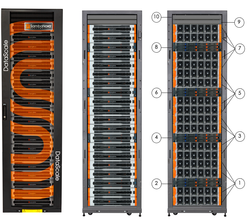
The DataScale SN10-8 system is self-contained in a standard 42 rack unit (RU) datacenter rack and may be purchased in various configurations depending on customer requirements, including any specific datacenter requirements that must be met. System population begins at the bottom of the rack with node 1 and increments up the rack. Network switches and other equipment are installed at the top of the rack.
A DataScale SN10-8 system consists of four DataScale SN10-2 RDU modules and an x86-based DataScale SN10-H server host module running either Red Hat® Enterprise Linux® or Ubuntu® Linux. Each DataScale SN10-2 module contains two Reconfigurable Data Units™ (RDUs), for a total of eight RDUs per DataScale SN10-8 system, and they are managed by the SambaNova’s SambaFlow™ software stack running on the host. Both the DataScale SN10-2 RDU module and the DataScale SN10-H module are 2RU chassis.
Switch equipment at the top of the rack provides a data network and an access network. Figure 1 and Table 1 identify the main components in the DataScale SN10-8.
| No. | Component |
|---|---|
1 |
System 1 SN10-8 (four SN10-2) |
2 |
System 1 SN10-8 (SN10-H) |
3 |
System 2 SN10-8 (four SN10-2) |
4 |
System 2 SN10-8 (SN10-H) |
5 |
System 3 SN10-8 (four SN10-2) |
6 |
System 3 SN10-8 (SN10-H) |
7 |
System 4 SN10-8 (four SN10-2) |
8 |
System 4 SN10-8 (SN10-H) |
9 |
Juniper® QFX5200-32c Ethernet (fan-side) |
10 |
Lantronix® serial console server (Juniper EX4300 behind) |
4. DataScale SN10-8R cabling
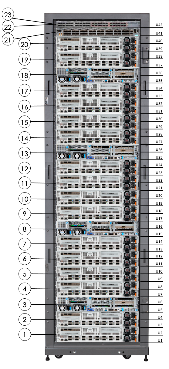
The DataScale SN10-8R internal components are delivered pre-configured and cabled in the 42RU rack. This section is for informational purposes only and to help identify what is cabled internally. Customers are not expected to interact with the internal cabling of the DataScale SN10-8R rack.
The only cables that customers are expected to interact with are for network and power components that need to be connected to the datacenter to provide power and connectivity to the DataScale SN10-8R.
Figure 2 and Table 2 below identify the locations of the main components in the DataScale SN10-8R (rear facing).
| No. | Component Description |
|---|---|
1 |
SN10-H-1-XRDU0 (system 1) |
2 |
SN10-H-1-XRDU1 (system 1) |
3 |
SN10-H-1 (system 1) |
4 |
SN10-H-1-XRDU2 (system 1) |
5 |
SN10-H-1-XRDU3 (system 1) |
6 |
SN10-H-2-XRDU0 (system 2) |
7 |
SN10-H-2-XRDU1 (system 2) |
8 |
SN10-H-2 (system 2) |
9 |
SN10-H-2-XRDU2 (system 2) |
10 |
SN10-H-2-XRDU3 (system 2) |
11 |
SN10-H-3-XRDU0 (system 3) |
12 |
SN10-H-3-XRDU1 (system 3) |
13 |
SN10-H 3 (system 3) |
14 |
SN10-H-3-XRDU2 (system 3) |
15 |
SN10-H-3-XRDU3 (system 3) |
16 |
SN10-H-4-XRDU0 (system 4) |
17 |
SN10-H-4-XRDU1 (system 4) |
18 |
SN10-H-4 (system 4) |
19 |
SN10-H-4-XRDU2 (system 4) |
20 |
SN10-H-4-XRDU3 (system 4) |
21 |
Juniper QFX5200-32c Ethernet (default) high-bandwidth data switch |
22 |
Juniper EX4300 access switch |
23 |
Lantronix serial console server |
0RU PDUs (not shown) are on the right side of the rack when facing the rack rear |
|
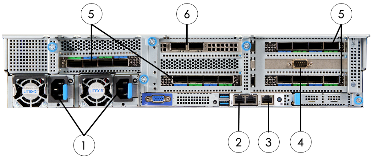
4.1. Cabling system components
The DataScale SN10-8R comes pre-configured and cabled with the purchased number of systems connected to the appropriate switches and switch ports.
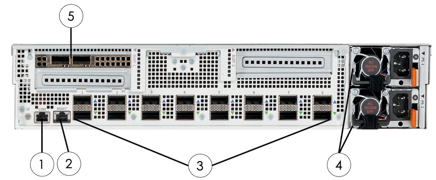
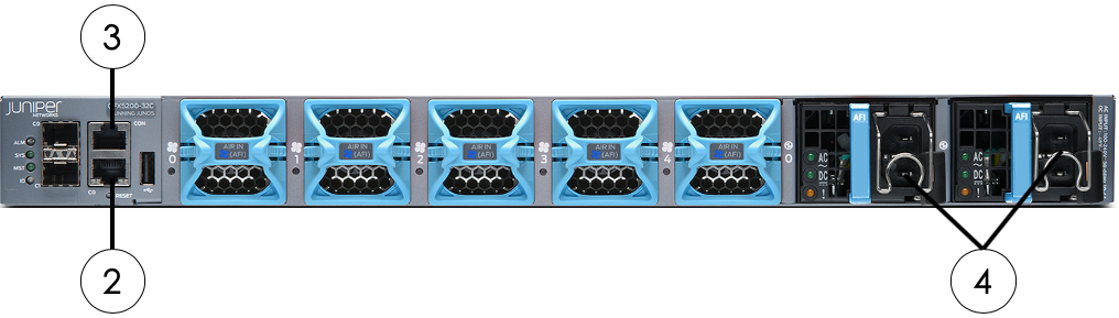
Figure 3, Figure 4, Table 3, and Table 4 below identify the components that will either be connected to switches or inter-connected to other system components.
| No. | Component | Connector/Cable Type |
|---|---|---|
1 |
Two power inlets |
C13 to C14 power cord |
2 |
SN10-H Net0 1GbE LAN |
RJ45, Cat5e or higher |
3 |
SN10-H 10/100/1000 management LAN (labeled “M”) |
RJ45, Cat5e or higher |
4 |
DB9 serial connection |
Rollover DB9F to RJ45 console cable |
5 |
Host interface card (HIC) |
QSFP-DD cable |
6 |
High-bandwidth network ports |
100GbE QSFP28 DAC cable |
| No. | Component | Connector/Cable Type |
|---|---|---|
1 |
SN10-2 COM serial port (COM) |
RJ45, Cat5e or higher |
2 |
SN10-2 10/100/1000 management LAN (MGMT) |
RJ45, Cat5e or higher |
3 |
Host HIC connections (8 pairs) |
QSFP-DD cable |
4 |
Two power inlets |
C13 to C14 power cord |
5 |
High-bandwidth network port connections |
100GbE QSFP28 DAC cable |
4.2. Serial console server cabling
The serial console server is installed and cabled in the factory. This component is located in RU42, and it occupies the front portion of the same rack unit as the Juniper EX4300 access switch. Cables used for this are standard Ethernet RJ45 cables and rollover DB9F to RJ45 console cables for the DataScale SN10-H systems.
A dedicated non-tagged VLAN network drop, that is on the access/management network, is required for the serial console server. This connection goes to the serial console server management port indicated by the number 1 in Figure 5 below. This ensures there is still network connectivity to the serial console server if anything should happen to the Juniper EX4300 access switch.
| Please note that ports for this device are not visible or accessible to the user due to the physical location of the unit in front of the access switch. This device is primarily intended for SambaNova service operations. |
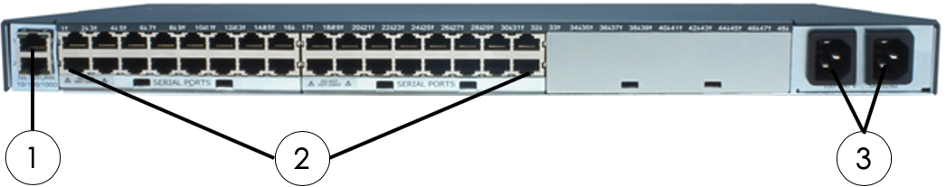
| No. | Component | Connector/Cable Type |
|---|---|---|
1 |
10/100/1000 management Network (labeled “1”) |
RJ45, Cat5e or higher |
2 |
Serial RJ45 connections (ports 1–32) |
RJ45, Ethernet cable |
3 |
Two power inlets |
C13 to C14 power cord |
Cabling requirements from the Lantronix serial console server to the other DataScale SN10-8 rack components are listed in Table 6 below.
| From Serial Console Server Port | To Component | Component Location | Component Port |
|---|---|---|---|
1 |
Juniper EX4300 |
RU42 |
CON2 |
2 |
Juniper QFX5200 Ethernet |
RU41 |
CON (Juniper) |
3 |
PDU 1 |
Right side of rack, closest to the rack front |
RJ45 just left of USB labeled “10101” |
4 |
PDU 2 |
Right side of rack, closest to the rack rear |
RJ45 just left of USB labeled “10101” |
5 |
- |
- |
- |
6 |
- |
- |
- |
7 |
SN10-H-4-XRDU3 |
RU39/RU40 |
COM |
8 |
SN10-H-4-XRDU2 |
RU37/RU18 |
COM |
9 |
SN10-H-4 |
RU35/RU36 |
DB9 male PCI card |
10 |
SN10-H-4-XRDU1 |
RU33/RU34 |
COM |
11 |
SN10-H-4-XRDU0 |
RU31/RU32 |
COM |
12 |
SN10-H-3-XRDU3 |
RU29/RU30 |
COM |
13 |
SN10-H-3-XRDU2 |
RU27/RU28 |
COM |
14 |
SN10-H-3 |
RU25/RU26 |
DB9 male PCI card |
15 |
SN10-H-3-XRDU1 |
RU23/RU24 |
COM |
16 |
SN10-H-3-XRDU0 |
RU21/RU22 |
COM |
17 |
SN10-H-2-XRDU3 |
RU19/RU20 |
COM |
18 |
SN10-H-2-XRDU2 |
RU17/RU18 |
COM |
19 |
SN10-H-2 |
RU15/RU16 |
DB9 male PCI card |
20 |
SN10-H-2-XRDU1 |
RU13/RU14 |
COM |
21 |
SN10-H-2-XRDU0 |
RU11/RU12 |
COM |
22 |
SN10-H-1-XRDU3 |
RU9/RU10 |
COM |
23 |
SN10-H-1-XRDU2 |
RU7/RU8 |
COM |
24 |
SN10-H-1 |
RU5/RU6 |
DB9 male PCI card |
25 |
SN10-H-1-XRDU1 |
RU3/RU4 |
COM |
26 |
SN10-H-1-XRDU0 |
RU1/RU2 |
COM |
27-32 |
- |
- |
- |
4.3. Access switch cabling
The Juniper EX4300 switch used for the access networks is installed and cabled in the factory. This component is located in RU42 at the rear of the rack and is shared in the same rack unit as the Lantronix serial console server. Cables used for this are standard Cat6 Ethernet RJ45 cables. This switch can further be segregated using port-based VLANs to separate access to the management interfaces of the DataScale SN10-8R components and the SN10-Hs’ operating system(OS) interface. The customer is responsible to configure this added network segregation. Please refer to Table 8 for what device is connected to which port, and available ports that can be used if an additional network drop is required for the separate network. This port separation can be configured by SambaNova if requested during initial deployment.
| Warning: When configuring the access switch to separate the management interfaces and the SN10-H OS interfaces with port-based VLANs, a separate network drop must be used for each network. Be aware that if the switch is reset to factory default for whatever reason, the VLAN configuration is lost. This could result in spanning-tree protocols disabling one or both of the networks. By default, the access switch is configured for Rapid Spanning Tree Protocol (RSTP). |
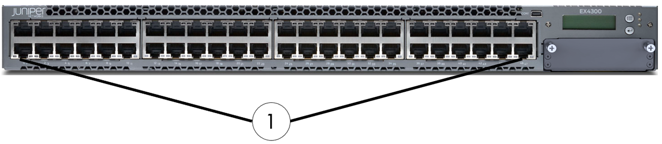
| No. | Component | Connector/Cable Type |
|---|---|---|
1 |
1GbE ports (Ports 0–47) |
RJ45, Cat5e or higher |
2 |
RJ45 console port |
RJ45, Cat5e or higher |
3 |
Network management port for em0 |
RJ45, Cat5e or higher |
4 |
Two power inlets |
C13 to C14 power cord |
Cabling requirements from the Juniper EX4300 switch for the access network to the other DataScale SN10-8 rack components are listed in Table 8.
| From Access Switch Port |
To Component | Component Location | Component Port |
|---|---|---|---|
0 |
- |
- |
- |
1 |
Juniper EX4300 access switch |
RU42 |
MGMT |
2 |
Juniper QFX5200-32c Ethernet |
RU41 |
C0 |
3 |
SN10-H-1-XRDU0 (system 1) |
RU1/RU2 |
MGMT |
4 |
SN10-H-1-XRDU1 (system 1) |
RU3/RU4 |
MGMT |
5 |
SN10-H-1-XRDU2 (system 1) |
RU7/RU8 |
MGMT |
6 |
SN10-H-1-XRDU3 (system 1) |
RU9/RU10 |
MGMT |
7 |
SN10-H-2-XRDU0 (system 2) |
RU11/RU12 |
MGMT |
8 |
SN10-H-2-XRDU1 (system 2) |
RU13/RU14 |
MGMT |
9 |
SN10-H-2-XRDU2 (system 2) |
RU17/RU18 |
MGMT |
10 |
SN10-H-2-XRDU3 (system 2) |
RU19/RU20 |
MGMT |
11 |
SN10-H-3-XRDU0 (system 3) |
RU21/RU22 |
MGMT |
12 |
SN10-H-3-XRDU1 (system 3) |
RU23/RU24 |
MGMT |
13 |
SN10-H-3-XRDU2 (system 3) |
RU27/RU28 |
MGMT |
14 |
SN10-H-3-XRDU3 (system 3) |
RU29/RU30 |
MGMT |
15 |
SN10-H-4-XRDU0 (system 4) |
RU31/RU32 |
MGMT |
16 |
SN10-H-4-XRDU1 (system 4) |
RU33/RU34 |
MGMT |
17 |
SN10-H-4-XRDU2 (system 4) |
RU37/RU38 |
MGMT |
18 |
SN10-H-4-XRDU3 (system 4) |
RU39/RU40 |
MGMT |
19-26 |
- |
- |
- |
27 |
PDU 1 |
Right side of rack, closest to the rack front |
RJ45 labeled |
28 |
PDU 2 |
Right side of rack, closest to the rack rear |
RJ45 Labeled |
29 |
- |
- |
- |
30 |
SN10-H-1 |
RU5/RU6 |
Labeled “M” |
31 |
SN10-H-2 |
RU15/RU16 |
Labeled “M” |
32 |
SN10-H-3 |
RU25/RU26 |
Labeled “M” |
33 |
SN10-H-4 |
RU35/RU36 |
Labeled “M” |
34-39 |
- |
- |
- |
40 |
Management Network Uplink |
- |
- |
41 |
Access Network Uplink |
- |
- |
42 |
- |
- |
- |
43 |
SN10-H-1 |
RU5/RU6 |
Left port Net0 |
44 |
SN10-H-2 |
RU15/RU16 |
Left port Net0 |
45 |
SN10-H-3 |
RU25/RU26 |
Left port Net0 |
46 |
SN10-H-4 |
RU35/RU36 |
Left port Net0 |
47 |
Access and Management Network Uplink |
- |
- |
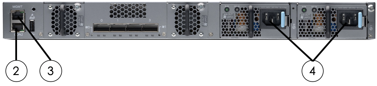
4.4. High-bandwidth data switch cabling
The DataScale SN10-8R is configured with the Juniper QFX5200-32C 100GbE Ethernet switch.
4.4.1. High-bandwidth Ethernet switch
The Juniper QFX5200-32C switch, which is the standard high-bandwidth data switch in the DataScale SN10-8R, is installed and cabled in the factory. This switch is located in RU41.
| No. | Component | Connector/Cable Type |
|---|---|---|
1 |
100GbE ports (ports 0–31) |
QSFP28 (or compatible) |
2 |
Network management port for em0 |
RJ45, Cat5e or higher |
3 |
RJ45 console port connection (CON) |
RJ45, Ethernet serial cable |
4 |
Two power inlets |
C13 to C14 power cord |
4.5. SN10-H and SN10-2 high-bandwidth network cabling
The high-bandwidth cabling for the SN10-Hs and SN10-2 systems is installed in the factory before delivery. The cabling used for this is high-bandwidth TwinAx cables.
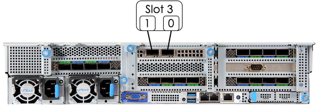
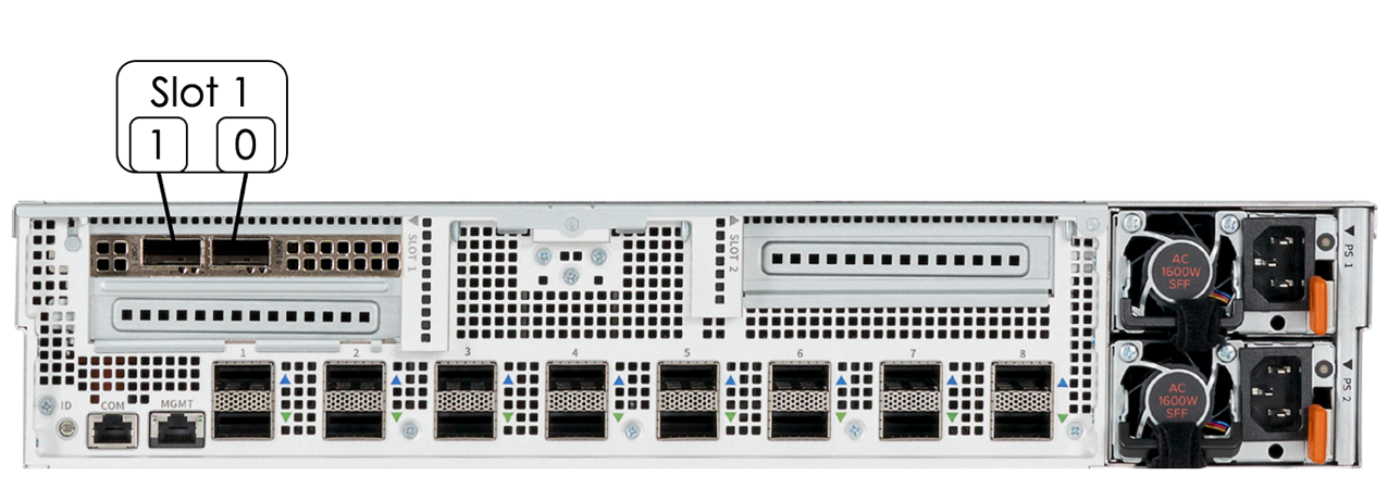
Cabling requirements from the Juniper QFX5200-32c Ethernet switch for the high-bandwidth data network to the other DataScale SN10-8R components are listed in the table below.
| From Data Network Switch Port | To Component | Component Location | Component Port |
|---|---|---|---|
0 |
SN10-H-1-XRDU0 (system 1) |
RU1/RU2 |
PCIe slot 1 - Port 0 |
1 |
SN10-H-1-XRDU1 (system 1) |
RU3/RU4 |
PCIe slot 1 - Port 0 |
2 |
SN10-H-1 (system 1) |
RU5/RU6 |
PCIe slot 3 - Port 0 |
3 |
SN10-H-1-XRDU2 (system 1) |
RU7/RU8 |
PCIe slot 1 - Port 0 |
4 |
SN10-H-1-XRDU3 (system 1) |
RU9/RU10 |
PCIe slot 1 - Port 0 |
5 |
SN10-H-2-XRDU0 (system 2) |
RU11/RU12 |
PCIe slot 1 - Port 0 |
6 |
SN10-H-2-XRDU1 (system 2) |
RU13/RU14 |
PCIe slot 1 - Port 0 |
7 |
SN10-H-2 (system 1) |
RU15/RU16 |
PCIe slot 3 - Port 0 |
8 |
SN10-H-2-XRDU2 (system 2) |
RU17/RU18 |
PCIe slot 1 - Port 0 |
9 |
SN10-H-1-XRDU3 (system 2) |
RU19/RU20 |
PCIe slot 1 - Port 0 |
10 |
SN10-H-3-XRDU0 (system 3) |
RU21/RU23 |
PCIe slot 1 - Port 0 |
11 |
SN10-H-3-XRDU1 (system 3) |
RU23/RU24 |
PCIe slot 1 - Port 0 |
12 |
SN10-H-3 (system 3) |
RU25/RU26 |
PCIe slot 3 - Port 0 |
13 |
SN10-H-3-XRDU2 (system 3) |
RU27/RU28 |
PCIe slot 1 - Port 0 |
14 |
SN10-H-3-XRDU3 (system 3) |
RU29/RU30 |
PCIe slot 1 - Port 0 |
15 |
SN10-H-4-XRDU0 (system 4) |
RU31/RU32 |
PCIe slot 1 - Port 0 |
16 |
SN10-H-4-XRDU1 (system 1) |
RU33/RU34 |
PCIe slot 1 - Port 0 |
17 |
SN10-H-4 (system 1) |
RU35/RU36 |
PCIe slot 3 - Port 0 |
18 |
SN10-H-4-XRDU2 (system 4) |
RU37/RU38 |
PCIe slot 1 - Port 0 |
19 |
SN10-H-4-XRDU3 (system 4) |
RU39/RU40 |
PCIe slot 1 - Port 0 |
27–30 |
LAG uplinks to customer data network |
- |
- |
31 |
Non-LAG uplink to customer data network |
- |
- |
4.6. Intra-system SN10-2 and SN10-H cabling
Intra-system cabling is installed in the factory before delivery. These cables are not intended to be user serviceable. Intra-system SN10-H-to-SN10-2 and SN10-2-to-SN10-2 cables are specially designed QSFP-DD terminated cable pairs.
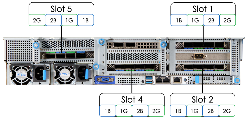
| Please note that the port numbering for a slot 5 cards is reversed. This is because the PCIe card orientation is different from the other cards. |
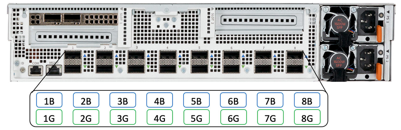
For cabling between the SN10-H server and the SN10-2 modules in a system, the ports are grouped with a blue and green pair. For example, the SN10-2 module’s port 1 consists of an upper blue port 1 and lower green port 1. This is highlighted in Figure 13.
For the SN10-H, there are two pairs of color-coded ports per PCIe card slot with only one of the pairs being used. For example, in slot 1 of an SN10-H, 1B and 1G are used for port pair 1 with 2B and 2G used for port pair 2, but for this particular card, only port pair 1 is used. This is shown in Figure 14.
In general, cabling between the SN10-H and the SN10-2s in a system looks as follows:
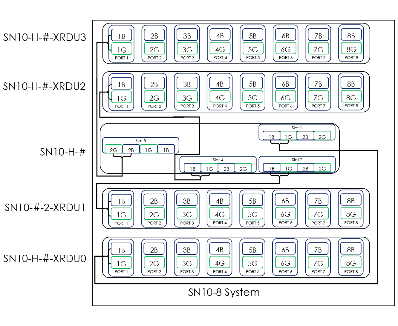
Where identified, the source blue port from the identified PCIe slot in the host goes to the corresponding target blue port 1 in the identified SN10-2s. Similarly, the source green port from the identified PCIe slot in the host goes to the corresponding target green port in the identified SN10-2. For example, from the host’s PCIe slot 1, slot 1 – Blue (1B) goes to the second SN10-2 in the node: Port 1 – Blue (1B). Each cable connection is detailed in Table 11 below. Also note that the plug ends on the cables are also color-coded green or blue.
| From SN10-H | Location | From SN10-H Card - Port | To SN10-2 | Location | To SN10-2 Port |
|---|---|---|---|---|---|
SN10-H-1 |
RU5/RU6 |
Slot 1-1B |
SN10-H-1-XRDU0 |
RU1/RU2 |
1B |
SN10-H-1 |
RU5/RU6 |
Slot 1-1G |
SN10-H-1-XRDU0 |
RU1/RU2 |
1G |
SN10-H-1 |
RU5/RU6 |
Slot 2-1B |
SN10-H-1-XRDU1 |
RU3/RU4 |
1B |
SN10-H-1 |
RU5/RU6 |
Slot 2-1G |
SN10-H-1-XRDU1 |
RU3/RU4 |
1G |
SN10-H-1 |
RU5/RU6 |
Slot 4-1B |
SN10-H-1-XRDU2 |
RU7/RU8 |
1B |
SN10-H-1 |
RU5/RU6 |
Slot 4-1G |
SN10-H-1-XRDU2 |
RU7/RU8 |
1G |
SN10-H-1 |
RU5/RU6 |
Slot 5-2B |
SN10-H-1-XRDU3 |
RU9/RU10 |
1B |
SN10-H-1 |
RU5/RU6 |
Slot 5-2G |
SN10-H-1-XRDU3 |
RU9/RU10 |
1G |
SN10-H-2 |
RU15/RU16 |
Slot 1-1B |
SN10-H-2-XRDU0 |
RU13/RU14 |
1B |
SN10-H-2 |
RU15/RU16 |
Slot 1-1G |
SN10-H-2-XRDU0 |
RU13/RU14 |
1G |
SN10-H-2 |
RU15/RU16 |
Slot 2-1B |
SN10-H-2-XRDU1 |
RU17/RU18 |
1B |
SN10-H-2 |
RU15/RU16 |
Slot 2-1G |
SN10-H-2-XRDU1 |
RU17/RU18 |
1G |
SN10-H-2 |
RU15/RU16 |
Slot 3-2B |
SN10-H-2-XRDU2 |
RU11/RU12 |
1B |
SN10-H-2 |
RU15/RU16 |
Slot 3-2G |
SN10-H-2-XRDU2 |
RU11/RU12 |
1G |
SN10-H-2 |
RU15/RU16 |
Slot 4-1B |
SN10-H-2-XRDU3 |
RU19/RU20 |
1B |
SN10-H-2 |
RU15/RU16 |
Slot 4-1G |
SN10-H-2-XRDU3 |
RU19/RU20 |
1G |
SN10-H-3 |
RU25/RU26 |
Slot 1-1B |
SN10-H-3-XRDU0 |
RU23/RU24 |
1B |
SN10-H-3 |
RU25/RU26 |
Slot 1-1G |
SN10-H-3-XRDU0 |
RU23/RU24 |
1G |
SN10-H-3 |
RU25/RU26 |
Slot 2-1B |
SN10-H-3-XRDU1 |
RU28/RU29 |
1B |
SN10-H-3 |
RU25/RU26 |
Slot 2-1G |
SN10-H-3-XRDU1 |
RU28/RU29 |
1G |
SN10-H-3 |
RU25/RU26 |
Slot 3-2B |
SN10-H-3-XRDU2 |
RU21/RU22 |
1B |
SN10-H-3 |
RU25/RU26 |
Slot 3-2G |
SN10-H-3-XRDU2 |
RU21/RU22 |
1G |
SN10-H-3 |
RU25/RU26 |
Slot 4-1B |
SN10-H-3-XRDU3 |
RU29/RU30 |
1B |
SN10-H-3 |
RU25/RU26 |
Slot 4-1G |
SN10-H-3-XRDU3 |
RU29/RU30 |
1G |
SN10-H-4 |
RU35/RU36 |
Slot 1-1B |
SN10-H-4-XRDU0 |
RU33/RU34 |
1B |
SN10-H-4 |
RU35/RU36 |
Slot 1-1G |
SN10-H-4-XRDU0 |
RU33/RU34 |
1G |
SN10-H-4 |
RU35/RU36 |
Slot 2-1B |
SN10-H-4-XRDU1 |
RU37/RU38 |
1B |
SN10-H-4 |
RU35/RU36 |
Slot 2-1G |
SN10-H-4-XRDU1 |
RU37/RU38 |
1G |
SN10-H-4 |
RU35/RU36 |
Slot 3-2B |
SN10-H-4-XRDU2 |
RU31/RU32 |
1B |
SN10-H-4 |
RU35/RU36 |
Slot 3-2G |
SN10-H-4-XRDU2 |
RU31/RU32 |
1G |
SN10-H-4 |
RU35/RU36 |
Slot 4-1B |
SN10-H-4-XRDU3 |
RU39/RU40 |
1B |
SN10-H-4 |
RU35/RU36 |
Slot 4-1G |
SN10-H-4-XRDU3 |
RU39/RU40 |
1G |
4.7. SN10-2 to SN10-2 Intra-system cabling
For the intra-system cabling between SN10-2 systems, the ports are grouped with a blue and green pair. For example, port 1 consists of blue port 1 above and green port 1 beneath. This is highlighted in Figure 15.
In general, the intra-system cabling of a SN10-2 system to other SN10-2 systems is done as follows:
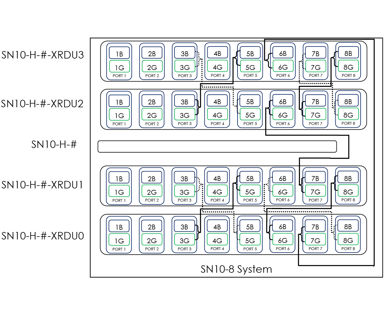
Where identified, the source blue port goes to the corresponding target blue port, and the source green port goes to the corresponding target green port. For example, from the first SN10-2 in a system, the Port 3 – Blue (3B) goes to the second SN10-2 in the system: Port 5 – Blue (5B). Each cable connection is detailed in the Table 12 below.
| From SN10-2 | Location | Port | To SN10-2 | Location | Port |
|---|---|---|---|---|---|
SN10-H-1-XRDU0 |
RU1/RU2 |
3B |
SN10-H-1-XRDU1 |
RU3/RU4 |
5B |
SN10-H-1-XRDU0 |
RU1/RU2 |
3G |
SN10-H-1-XRDU1 |
RU3/RU4 |
5G |
SN10-H-1-XRDU0 |
RU1/RU2 |
5B |
SN10-H-1-XRDU1 |
RU3/RU4 |
3B |
SN10-H-1-XRDU0 |
RU1/RU2 |
5G |
SN10-H-1-XRDU1 |
RU3/RU4 |
3G |
SN10-H-1-XRDU0 |
RU1/RU2 |
6B |
SN10-H-1-XRDU1 |
RU3/RU4 |
8B |
SN10-H-1-XRDU0 |
RU1/RU2 |
6G |
SN10-H-1-XRDU1 |
RU3/RU4 |
8G |
SN10-H-1-XRDU0 |
RU1/RU2 |
7B |
SN10-H-1-XRDU3 |
RU9/RU10 |
6B |
SN10-H-1-XRDU0 |
RU1/RU2 |
7G |
SN10-H-1-XRDU3 |
RU9/RU10 |
6G |
SN10-H-1-XRDU0 |
RU1/RU2 |
8B |
SN10-H-1-XRDU1 |
RU3/RU4 |
6B |
SN10-H-1-XRDU0 |
RU1/RU2 |
8G |
SN10-H-1-XRDU1 |
RU3/RU4 |
6G |
SN10-H-1-XRDU1 |
RU3/RU4 |
7B |
SN10-H-1-XRDU2 |
RU7/RU8 |
6B |
SN10-H-1-XRDU1 |
RU3/RU4 |
7G |
SN10-H-1-XRDU2 |
RU7/RU8 |
6G |
SN10-H-1-XRDU2 |
RU7/RU8 |
3B |
SN10-H-1-XRDU3 |
RU9/RU10 |
5B |
SN10-H-1-XRDU2 |
RU7/RU8 |
3G |
SN10-H-1-XRDU3 |
RU9/RU10 |
5G |
SN10-H-1-XRDU2 |
RU7/RU8 |
5B |
SN10-H-1-XRDU3 |
RU9/RU10 |
3B |
SN10-H-1-XRDU2 |
RU7/RU8 |
5G |
SN10-H-1-XRDU3 |
RU9/RU10 |
3G |
SN10-H-1-XRDU2 |
RU7/RU8 |
7B |
SN10-H-1-XRDU3 |
RU9/RU10 |
8B |
SN10-H-1-XRDU2 |
RU7/RU8 |
7G |
SN10-H-1-XRDU3 |
RU9/RU10 |
8G |
SN10-H-1-XRDU2 |
RU7/RU8 |
8B |
SN10-H-1-XRDU3 |
RU9/RU10 |
7B |
SN10-H-1-XRDU2 |
RU7/RU8 |
8G |
SN10-H-1-XRDU3 |
RU9/RU10 |
7G |
SN10-H-2-XRDU0 |
RU11/RU12 |
3B |
SN10-H-2-XRDU1 |
RU13/RU14 |
5B |
SN10-H-2-XRDU0 |
RU11/RU12 |
3G |
SN10-H-2-XRDU1 |
RU13/RU14 |
5G |
SN10-H-2-XRDU0 |
RU11/RU12 |
5B |
SN10-H-2-XRDU1 |
RU13/RU14 |
3B |
SN10-H-2-XRDU0 |
RU11/RU12 |
5G |
SN10-H-2-XRDU1 |
RU13/RU14 |
3G |
SN10-H-2-XRDU0 |
RU11/RU12 |
6B |
SN10-H-2-XRDU1 |
RU19/RU20 |
8B |
SN10-H-2-XRDU0 |
RU11/RU12 |
6G |
SN10-H-2-XRDU1 |
RU19/RU20 |
8G |
SN10-H-2-XRDU0 |
RU11/RU12 |
7B |
SN10-H-2-XRDU3 |
RU13/RU14 |
6B |
SN10-H-2-XRDU0 |
RU11/RU12 |
7G |
SN10-H-2-XRDU3 |
RU13/RU14 |
6G |
SN10-H-2-XRDU0 |
RU11/RU12 |
8B |
SN10-H-2-XRDU1 |
RU13/RU14 |
6B |
SN10-H-2-XRDU0 |
RU11/RU12 |
8G |
SN10-H-2-XRDU1 |
RU13/RU14 |
6G |
SN10-H-2-XRDU1 |
RU13/RU14 |
7B |
SN10-H-2-XRDU2 |
RU17/RU18 |
6B |
SN10-H-2-XRDU1 |
RU13/RU14 |
7G |
SN10-H-2-XRDU2 |
RU17/RU18 |
6G |
SN10-H-2-XRDU2 |
RU17/RU18 |
3B |
SN10-H-2-XRDU3 |
RU19/RU20 |
5B |
SN10-H-2-XRDU2 |
RU17/RU18 |
3G |
SN10-H-2-XRDU3 |
RU19/RU20 |
5G |
SN10-H-2-XRDU2 |
RU17/RU18 |
5B |
SN10-H-2-XRDU3 |
RU19/RU20 |
3B |
SN10-H-2-XRDU2 |
RU17/RU18 |
5G |
SN10-H-2-XRDU3 |
RU19/RU20 |
3G |
SN10-H-2-XRDU2 |
RU17/RU18 |
7B |
SN10-H-2-XRDU3 |
RU19/RU20 |
8B |
SN10-H-2-XRDU2 |
RU17/RU18 |
7G |
SN10-H-2-XRDU3 |
RU19/RU20 |
8G |
SN10-H-2-XRDU2 |
RU17/RU18 |
8B |
SN10-H-2-XRDU3 |
RU19/RU20 |
7B |
SN10-H-2-XRDU2 |
RU17/RU18 |
8G |
SN10-H-2-XRDU3 |
RU19/RU20 |
7G |
SN10-H-3-XRDU0 |
RU21/RU22 |
3B |
SN10-H-3-XRDU1 |
RU23/RU24 |
5B |
SN10-H-3-XRDU0 |
RU21/RU22 |
3G |
SN10-H-3-XRDU1 |
RU23/RU24 |
5G |
SN10-H-3-XRDU0 |
RU21/RU22 |
5B |
SN10-H-3-XRDU1 |
RU23/RU24 |
3B |
SN10-H-3-XRDU0 |
RU21/RU22 |
5G |
SN10-H-3-XRDU1 |
RU23/RU24 |
3G |
SN10-H-3-XRDU0 |
RU21/RU22 |
6B |
SN10-H-3-XRDU1 |
RU23/RU24 |
8B |
SN10-H-3-XRDU0 |
RU21/RU22 |
6G |
SN10-H-3-XRDU1 |
RU23/RU24 |
8G |
SN10-H-3-XRDU0 |
RU21/RU22 |
7B |
SN10-H-3-XRDU3 |
RU23/RU24 |
6B |
SN10-H-3-XRDU0 |
RU21/RU22 |
7G |
SN10-H-3-XRDU3 |
RU23/RU24 |
6G |
SN10-H-3-XRDU0 |
RU21/RU22 |
8B |
SN10-H-3-XRDU1 |
RU23/RU24 |
6B |
SN10-H-3-XRDU0 |
RU21/RU22 |
8G |
SN10-H-3-XRDU1 |
RU23/RU24 |
6G |
SN10-H-3-XRDU1 |
RU23/RU24 |
7B |
SN10-H-3-XRDU2 |
RU27/RU29 |
6B |
SN10-H-3-XRDU1 |
RU23/RU24 |
7G |
SN10-H-3-XRDU2 |
RU27/RU29 |
6G |
SN10-H-3-XRDU2 |
RU27/RU28 |
3B |
SN10-H-3-XRDU3 |
RU29/RU30 |
5B |
SN10-H-3-XRDU2 |
RU27/RU28 |
3G |
SN10-H-3-XRDU3 |
RU29/RU30 |
5G |
SN10-H-3-XRDU2 |
RU27/RU28 |
5B |
SN10-H-3-XRDU3 |
RU29/RU30 |
3B |
SN10-H-3-XRDU2 |
RU27/RU28 |
5G |
SN10-H-3-XRDU3 |
RU29/RU30 |
3G |
SN10-H-3-XRDU2 |
RU27/RU28 |
7B |
SN10-H-3-XRDU3 |
RU29/RU30 |
8B |
SN10-H-3-XRDU2 |
RU27/RU28 |
7G |
SN10-H-3-XRDU3 |
RU29/RU30 |
8G |
SN10-H-3-XRDU2 |
RU27/RU28 |
8B |
SN10-H-3-XRDU3 |
RU29/RU30 |
7B |
SN10-H-3-XRDU2 |
RU27/RU28 |
8G |
SN10-H-3-XRDU3 |
RU29/RU30 |
7G |
SN10-H-4-XRDU0 |
RU31/RU32 |
3B |
SN10-H-4-XRDU1 |
RU33/RU34 |
5B |
SN10-H-4-XRDU0 |
RU31/RU32 |
3G |
SN10-H-4-XRDU1 |
RU33/RU34 |
5G |
SN10-H-4-XRDU0 |
RU31/RU32 |
5B |
SN10-H-4-XRDU1 |
RU33/RU34 |
3B |
SN10-H-4-XRDU0 |
RU31/RU32 |
5G |
SN10-H-4-XRDU1 |
RU33/RU34 |
3G |
SN10-H-4-XRDU0 |
RU31/RU32 |
6B |
SN10-H-4-XRDU1 |
RU33/RU34 |
8B |
SN10-H-4-XRDU0 |
RU31/RU32 |
6G |
SN10-H-4-XRDU1 |
RU33/RU34 |
8G |
SN10-H-4-XRDU0 |
RU31/RU32 |
7B |
SN10-H-4-XRDU3 |
RU33/RU34 |
6B |
SN10-H-4-XRDU0 |
RU31/RU32 |
7G |
SN10-H-4-XRDU3 |
RU33/RU34 |
6G |
SN10-H-4-XRDU0 |
RU31/RU32 |
8B |
SN10-H-4-XRDU1 |
RU33/RU34 |
6B |
SN10-H-4-XRDU0 |
RU31/RU32 |
8G |
SN10-H-4-XRDU1 |
RU33/RU34 |
6G |
SN10-H-4-XRDU1 |
RU33/RU34 |
7B |
SN10-H-4-XRDU2 |
RU37/RU38 |
6B |
SN10-H-4-XRDU1 |
RU33/RU34 |
7G |
SN10-H-4-XRDU2 |
RU37/RU38 |
6G |
SN10-H-4-XRDU2 |
RU37/RU38 |
3B |
SN10-H-4-XRDU3 |
RU39/RU40 |
5B |
SN10-H-4-XRDU2 |
RU37/RU38 |
3G |
SN10-H-4-XRDU3 |
RU39/RU40 |
5G |
SN10-H-4-XRDU2 |
RU37/RU38 |
5B |
SN10-H-4-XRDU3 |
RU39/RU40 |
3B |
SN10-H-4-XRDU2 |
RU37/RU38 |
5G |
SN10-H-4-XRDU3 |
RU39/RU40 |
3G |
SN10-H-4-XRDU2 |
RU37/RU38 |
7B |
SN10-H-4-XRDU3 |
RU39/RU40 |
8B |
SN10-H-4-XRDU2 |
RU37/RU38 |
7G |
SN10-H-4-XRDU3 |
RU39/RU40 |
8G |
SN10-H-4-XRDU2 |
RU37/RU38 |
8B |
SN10-H-4-XRDU3 |
RU39/RU40 |
7B |
SN10-H-4-XRDU2 |
RU37/RU38 |
8G |
SN10-H-4-XRDU3 |
RU39/RU40 |
7G |
4.8. Power cabling the DataScale SN10-8R
There are two power distribution units (PDUs) installed in the DataScale SN10-8R that provide redundant power in case of a single PDU failure. They are located on the right side of the rack when you are facing the rear of the rack. Table 13 below details the PDU identification and location within the rack.
| PDU Identification | Location in Rack (facing rack rear) |
|---|---|
PDU1 |
Right side of rack, closest to the rack front/closest to the systems |
PDU2 |
Right side of rack, closest to the rack rear/furthest from the systems |
Depending on the number of systems in the DataScale SN10-8R, port population of the PDUs will vary, but the same outlets are always used for the same systems regardless of rack configuration. Table 14 below shows all the needed connections for a four-system rack, but it also applies to a rack with fewer populated systems. DataScale SN10-8R are delivered pre-installed with power cables from the factory.
| Unused ports must NOT be used for any reason, and only the designated ports should be used. This prevents overloading of breaker circuits in the PDU and unexpected outages. |
| From Rack Unit | From Component | To PDU1 Port | To PDU2 Port |
|---|---|---|---|
42 |
Lantronix console server PSU1 (left PSU when facing rear of Lantronix) |
1 |
|
42 |
Lantronix console server PSU2 (right PSU when facing rear of Lantronix) |
1 |
|
42 |
Juniper EX4300 access switch PSU 1 (Left PSU when facing rear of switch) |
2 |
|
42 |
Juniper EX4300 access switch PSU 2 (right PSU when facing rear of switch) |
2 |
|
41 |
Juniper QFX5200-32c Eth PSU 1 (left PSU when facing rear of switch) |
3 |
|
41 |
Juniper QFX5200-32c Eth PSU 2 (right PSU when facing rear of switch) |
3 |
|
40 |
SN10-H-4-XRDU3 top PSU (four-system) |
4 |
|
39 |
SN10-H-4-XRDU3 bottom PSU (four-system) |
4 |
|
38 |
SN10-H-4-XRDU2 top PSU (four-system) |
6 |
|
37 |
SN10-H-4-XRDU2 bottom PSU (four-system) |
6 |
|
35 |
SN10-H-4 left PSU (four-system) |
9 |
|
35 |
SN10-H-4 right PSU (four-system) |
9 |
|
34 |
SN10-H-4-XRDU1 top PSU (four-system) |
7 |
|
33 |
SN10-H-4-XRDU1 bottom PSU (four-system) |
7 |
|
32 |
SN10-H-4-XRDU0 top PSU (four-system) |
8 |
|
31 |
SN10-H-4-XRDU0 bottom PSU (four-system) |
8 |
|
30 |
SN10-H-3-XRDU3 top PSU (three-system) |
11 |
|
29 |
SN10-H-3-XRDU3 bottom PSU (three-system) |
11 |
|
28 |
SSN10-H-3-XRDU2 top PSU (three-system) |
13 |
|
27 |
SN10-H-3-XRDU2 bottom PSU (three-system) |
13 |
|
25 |
SN10-H-3 left PSU (three-system) |
16 |
|
25 |
SN10-H-3 right PSU (three-system) |
16 |
|
24 |
SN10-H-3-XRDU1 top PSU (three-system) |
14 |
|
23 |
SN10-H-3-XRDU1 bottom PSU (three-system) |
14 |
|
22 |
SN10-H-3-XRDU0 top PSU (three-system) |
15 |
|
21 |
SN10-H-3-XRDU0 bottom PSU (three-system) |
15 |
|
20 |
SN10-H-2-XRDU3 top PSU (two-system) |
17 |
|
19 |
SN10-H-2-XRDU3 bottom PSU (two-system) |
17 |
|
18 |
SN10-H-2-XRDU2 top PSU (two-system) |
19 |
|
17 |
SN10-H-2-XRDU2 bottom PSU (two-system) |
19 |
|
15 |
SN10-H-2 left PSU (two-system) |
20 |
|
15 |
SN10-H-2 right PSU (two-system) |
20 |
|
14 |
SN10-H-2-XRDU1 PSU (two-system) |
21 |
|
13 |
SN10-H-2-XRDU1 bottom PSU (two-system) |
21 |
|
12 |
SN10-H-2-XRDU0 top PSU (two-system) |
22 |
|
11 |
SN10-H-2-XRDU0 bottom PSU (two-system) |
22 |
|
10 |
SN10-H-1-XRDU3 top PSU (one-system) |
23 |
|
9 |
SN10-H-1-XRDU3 bottom PSU (one-system) |
23 |
|
8 |
SN10-H-1-XRDU2 top PSU (one-system) |
24 |
|
7 |
SN10-H-1-XRDU2 bottom PSU (one-system) |
24 |
|
5 |
SN10-H-1 left PSU (one-system) |
25 |
|
5 |
SN10-H-1 right PSU (one-system) |
25 |
|
4 |
SN10-H-1-XRDU1 top PSU (one-system) |
27 |
|
3 |
SN10-H-1-XRDU1 bottom PSU (one-system) |
27 |
|
2 |
SN10-H-1-XRDU0 top PSU (one-system) |
29 |
|
1 |
SN10-H-1-XRDU0 bottom PSU (one-system) |
29 |
5. Site preparation for DataScale SN10-8R installation
Please ensure the following specifications are met regarding physical space, power, cooling, networking, and cabling when preparing a site for rack installation.
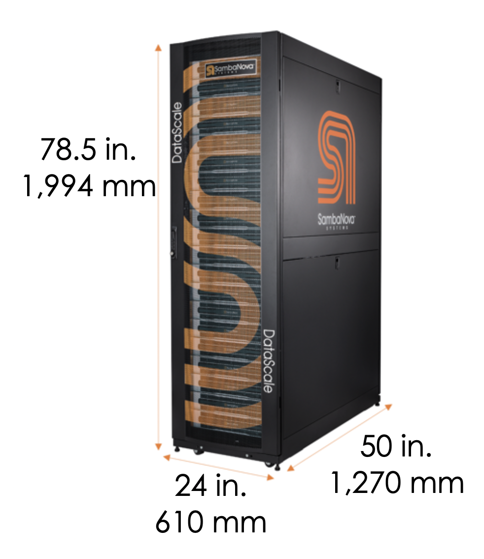
5.1. Physical specifications for each DataScale SN10-8R
| Description | English | Metric |
|---|---|---|
Height |
78.5 in. |
1,994 mm |
Width |
24 in. |
610 mm |
Depth |
50 in. |
1,270 mm |
Packaged shipping height |
88.5 in. |
2,248 mm |
Packaged shipping width |
42 in. |
1,067 mm |
Packaged shipping depth |
64 in. |
1,626 mm |
| Description | English | Metric |
|---|---|---|
Minimum clearance cabinet top to overhead infrastructure |
24 in. |
610 mm |
Minimum clearance to front of rack for system installation and service |
32 in. |
812 mm |
Minimum clearance at rack rear for service |
24 in. |
610 mm |
| Configuration | Weight | Shipping Weight | ||
|---|---|---|---|---|
English |
Metric |
English |
Metric |
|
DataScale SN10-8R Quarter Rack |
755 lbs. |
343 kg |
1055 lbs. |
480 kg |
DataScale SN10-8R |
1065 lbs. |
484 kg |
1365 lbs. |
620 kg |
DataScale SN10-8R |
1665 lbs. |
756 kg |
2025 lbs. |
919 kg |
5.2. Power requirements
Power requirements depend on the specific rack you are installing. Your SambaNova representative will discuss power draw, facility power requirements, and grounding requirements when you fill out your site-specific forms.
5.3. Network requirements
The DataScale SN10-8R requires certain networks to be provided as well as to be managed and maintained. This section describes these networks and what is required from the customer.
5.3.1. Network architecture and layout
There are three general networks that are used within the DataScale SN10-8R:
-
Data network
-
Management
-
Access network
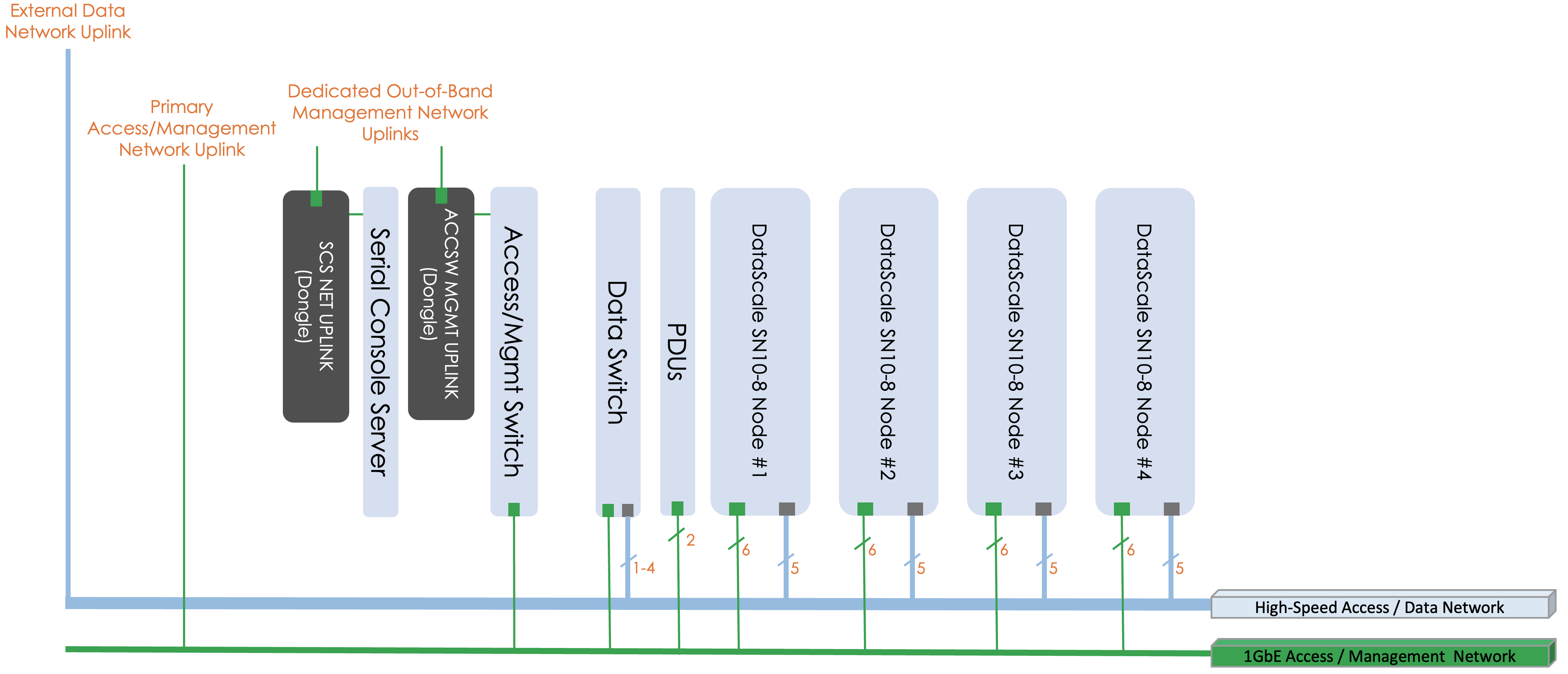
The data network is a high-bandwidth (100GbE) Ethernet network used for the RDUs and SN10-H to take in data from an external storage source and for inter-RDU communication.
The management network is a 1GbE network used to log in to the DataScale SN10-8R components. This network connects to each component’s baseboard management controller (BMC) for power control, configuration, and monitoring/debugging, as well to perform any other service operations. This network also connects to the systems’ SN10-H operating system (OS) to perform day-to-day user operations on the systems. This could include such operations as streaming logs, performing software updates, and performing other day-to-day system administration tasks.
Customers may choose to partition the access switch using port-based VLANs to separate access to the management interfaces of the DataScale SN10-8R components and the SN10-H OS interfaces. The customer is responsible for configuring this added network segregation. Please refer to Table 8 for device to port mappings, and available ports that can be used if an additional network drop is required for the separate network. Alternatively, customers may leverage the high-bandwidth data network for user access to the systems as well.
These networks should typically be allocated a separate subnet to ensure the isolation of traffic, to regulate access to these networks.
5.3.2. Network infrastructure requirements
A dedicated subnet and downlink should be allocated for each of the networks described in Section 5.3.1. A CIDR /26 subnet, or a subnet of 62 usable IP addresses, for the access network and a CIDR /27 subnet, or 30 usable IP addresses, for the data network provide sufficient IP addresses for each of the networks. There is an assumption that the first three IP addresses on each subnet will be dedicated for redundant customer network infrastructure (for example, gateway VIP, switch failover IPs, and so on).
In addition to the creation of these two subnets, three physical downlinks, two for the access network, and one for the data network need to be provided.
-
One downlink for the access network connects directly to the access switch.
-
The second downlink for the access network connects to the serial console server in the top of the DataScale SN10-8R as described in Section 4.2.
-
The downlink for the data network connects to the data switch.
The high-bandwidth switch may require that the customer configure multiple connections using a network aggregation (LACP/LAG) group in order to provide the necessary level of bandwidth to and from the rack. By default, only a single port is configured as an uplink. Details for each of these networks are described in the table below.
| Network | Switch | Uplink Port | Port Type |
|---|---|---|---|
Data (/27) |
Juniper QFX5200 data Ethernet switch (default) |
31 |
QSFP28 |
Access (/26) |
Juniper 1G access switch |
47 |
RJ45 |
Access (/26) |
Serial console server |
Dongle on left rear vertical bar of rack |
RJ45 |
|
To avoid potential spanning tree issues when initially connecting the rack to a customer network, do NOT plug in multiple uplinks from the data switch to the data network. Only the single uplink on port 31 of the Juniper data switch should be used initially. The default configuration of the switch has not been configured for the customer’s specific spanning tree configuration and multiple ports may lead to spanning tree issues. Once local switch administrators have implemented proper local spanning tree configurations on the Juniper data switch, multiple uplinks can be used. |
5.4. DataScale SN10-8R cabling
5.4.1. Cabling datacenter networks requirements
Prior to the delivery of the DataScale SN10-8R rack, ensure that the datacenter network and power cabling have been prepared.
-
Route the required network outlets from the datacenter network infrastructure to where the DataScale SN10-8R will be installed.
-
Ensure that the configurations described in Section 5.3 of this document have been completed.
-
It is good practice to label the cables that are used to connect the two networks to the DataScale SN10-8R.
5.4.2. Cabling datacenter power requirements
-
Route the needed power drops to where the DataScale SN10-8R will be installed.
-
Ensure the power drops meet the power requirements, socket type, and socket quantity described in Section 5.2 of this document.
6. Hardware installation tasks
Once the SambaNova DataScale SN10-8R is rolled to its location on the datacenter floor, perform the following:
-
Inspect the rack for any damage that may have resulted from local handling or relocation within the customer facility.
-
Allow the system to reside on the datacenter floor for 24 hours under ambient environmental conditions before powering on the rack. This allows the components to acclimatize to the environment, prevents the effects of sudden cooling or heating, and removes the possibility of any condensation accumulation.
-
Attach the rack’s bus grounding bar to the facility’s ground, as described in [Grounding requirements].
-
Typically, the rack should be permanently attached to the datacenter floor in its intended location using the tie-down brackets and bolts. Users should consult their facilities staff regarding preparing the tie-down bolt holes and locations. If it is standard procedure to lower the rack feet in each corner of the rack, please do so here.
-
Connect the datacenter network cable drop to the Juniper high-bandwidth data switch to ports 27-30 for LAG, per the table in Section 5.3.2. A single LAG port can be used. Please ensure that the switch that is connecting to this Juniper high-bandwidth data switch is configured for a LAG. If a LAG configured port is not available from the customer switch, please use port 31 on the Juniper high-bandwidth data switch.
-
Connect datacenter access / management network cable drops to the Juniper access switch per the table in Section 5.3.2.
-
Connect the second datacenter access network cable drop to the dongle on the left-rear vertical bar of the rack for the Lantronix serial console server management interface port, per Table 5 earlier in this document.
-
Connect the two power plugs from the PDUs to the two 3-phase power sockets, as described in [Facility power requirements].
-
Inspect the rack during power-on to make sure there are no issues with the PDUs or other rack components. Determine whether any warning LEDs on the rack components are lit. If warning or error lights appear, please refer to the support documentation for information on how to resolve the issue. Documentation can be found at https://support.sambanova.ai.
| The hardware installation tasks may be handled by the SambaNova onsite engineering team if that is requested. |