

SambaRack SN40L-16 Rack components (2 PDU configuration)
This table lists the primary components included at the rack level. These components provide compute capacity, networking, management access, and redundant power for the SambaRack SN40L-16 system.SambaRack SN40L-16 Node components – 2-PDU config
This table details the components that make up a single SambaRack SN40L-16 node. These components deliver accelerator compute capability and support system management and monitoring.
All racks ship with components pre-mounted, internal cabling connected, and filler panels installed.
Rack layout – 2-PDU config
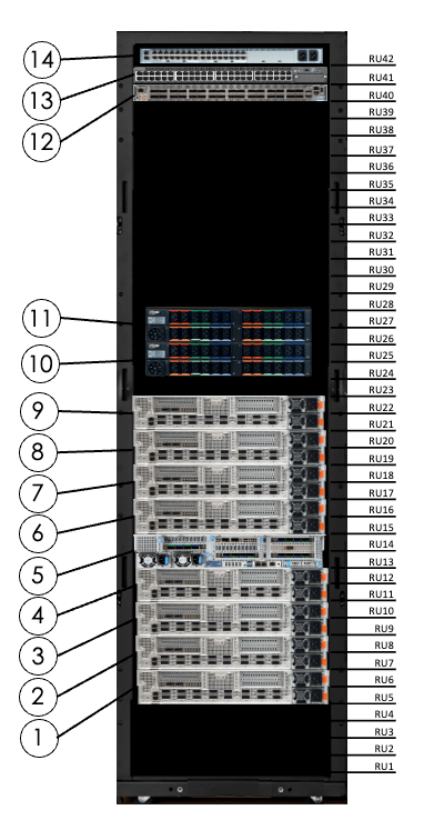
The figure below shows component locations from the rear of the rack. All cabling is performed at the rear.Component locations (rear view) – 2-PDU config
Compute components – 2-PDU config
SN40L-H host module – 2-PDU config
The host module manages accelerator operations and provides the primary interface to the rack’s compute resources.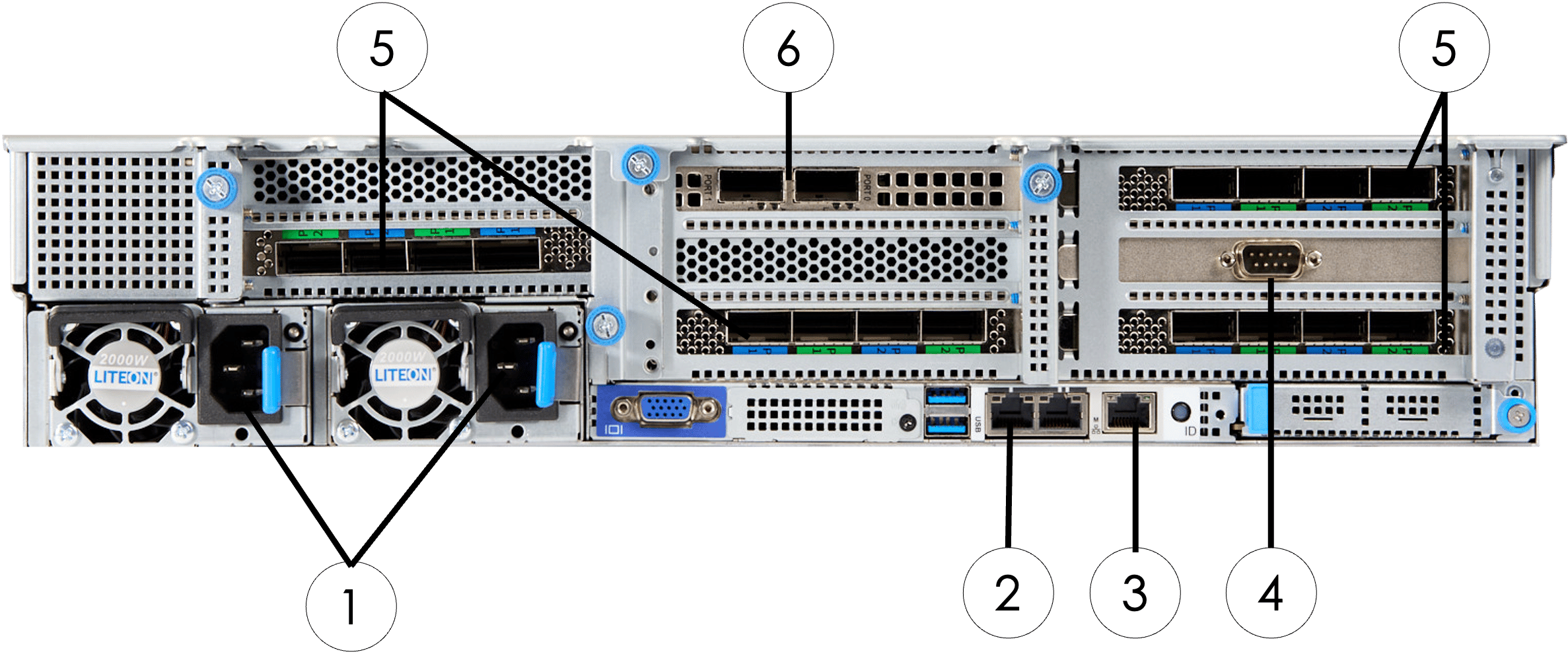
SN40L-2 XRDU module – 2-PDU config
Each XRDU module contains two RDUs and connects to both the management network and the high-bandwidth data network.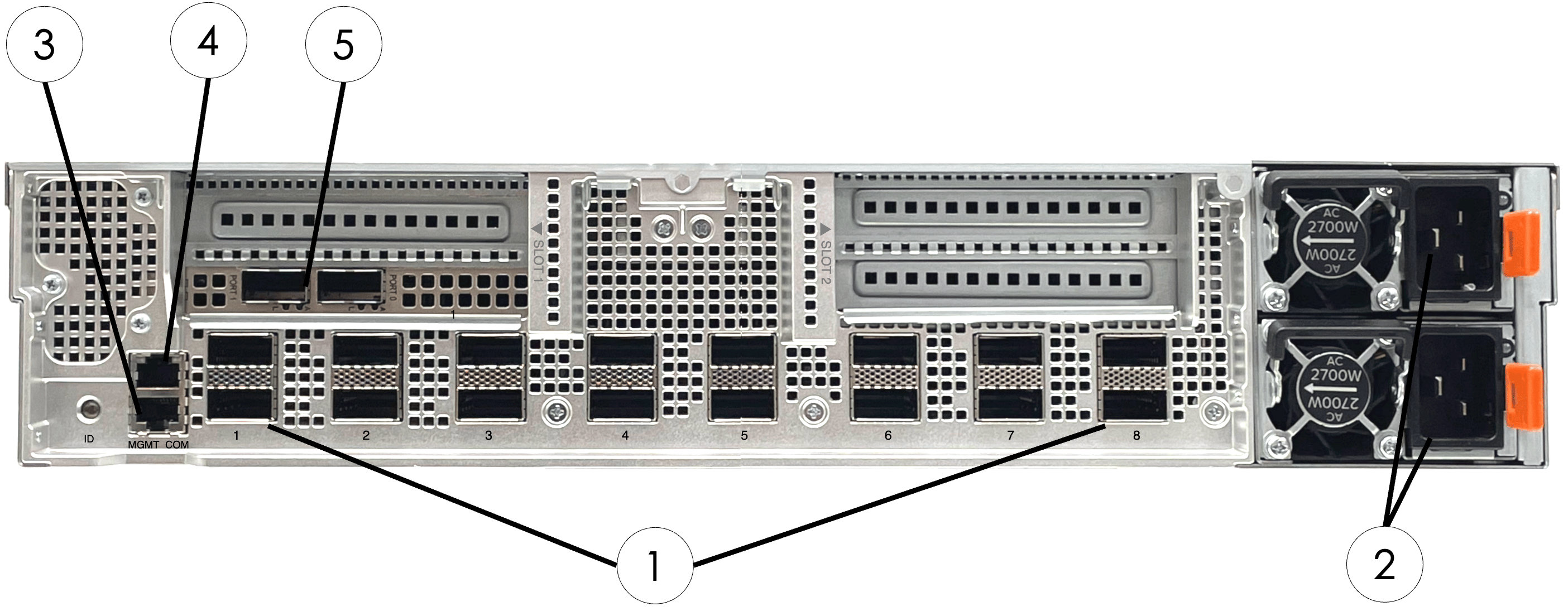
Networking components – 2-PDU config
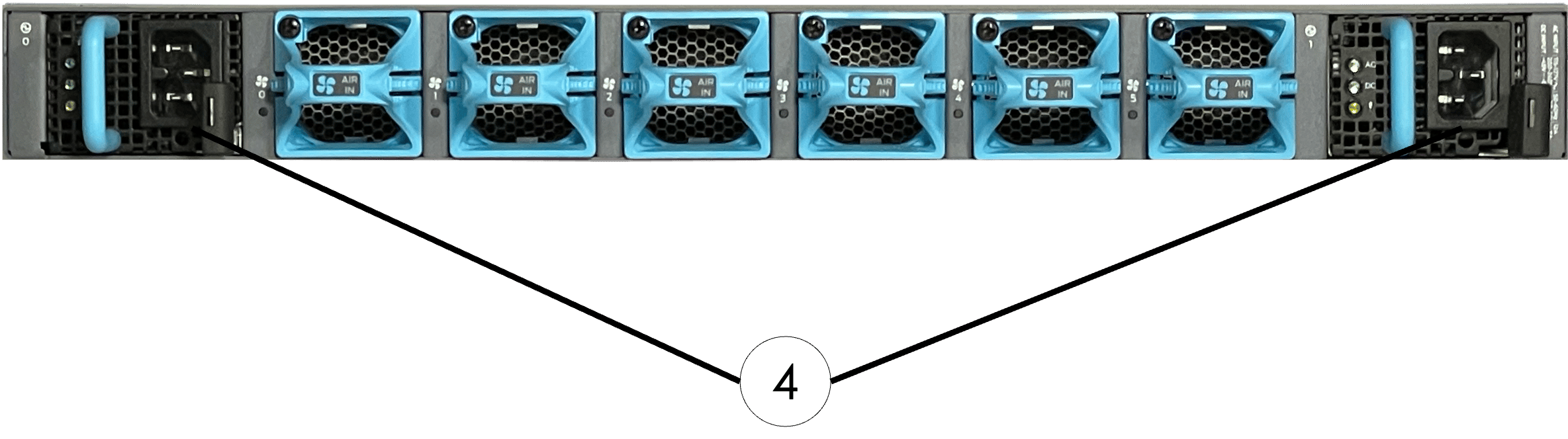
The rack includes three networking devices: a high-bandwidth data switch for inference traffic, a management switch for component administration, and a serial console server for out-of-band access.High-bandwidth data switch (Juniper QFX5130) – 2-PDU config
The QFX5130 provides 400GbE connectivity for all data path components. Connections to XRDUs and the host module use 400GbE to 2×200GbE DAC splitter cables, delivering 200GbE per endpoint.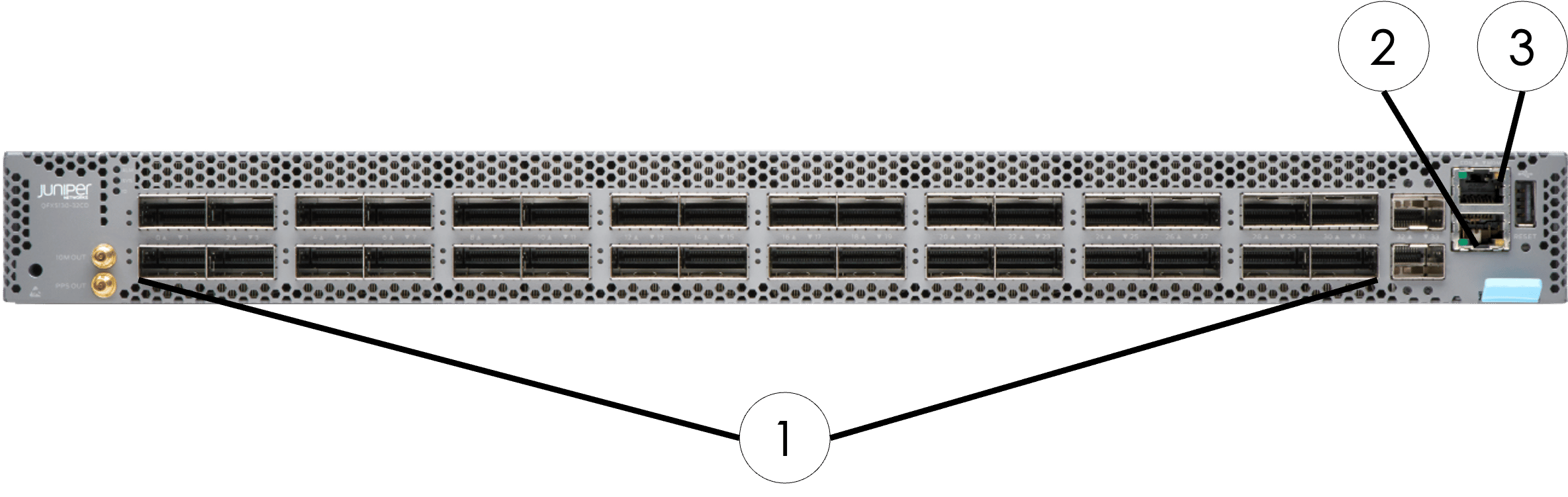
Port assignments – 2-PDU config (high-bandwidth switch)
The figures below show port assignments for the SN40L-H and SN40L-2 XRDUs. The table details all high-bandwidth data switch connections using 400GbE to 2×200GbE DAC splitter cables.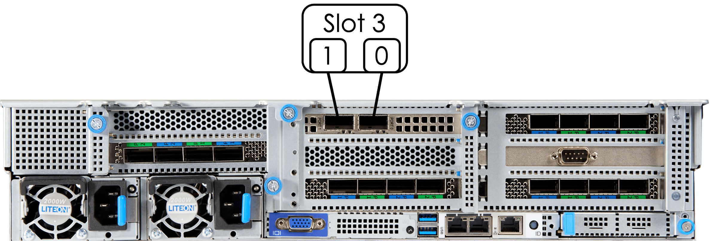
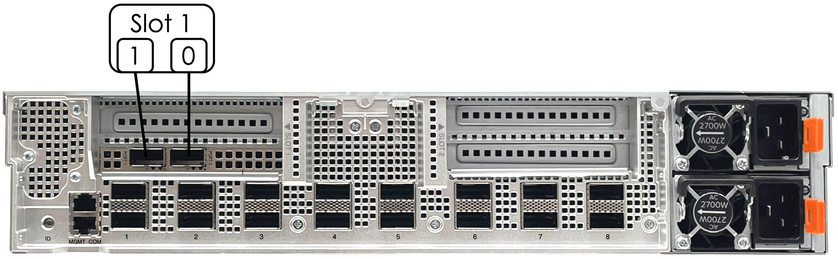
High-bandwidth data switch cabling is configured at the factory. Do not modify unless directed by SambaNova support.
Management switch (Juniper EX-series) – 2-PDU config
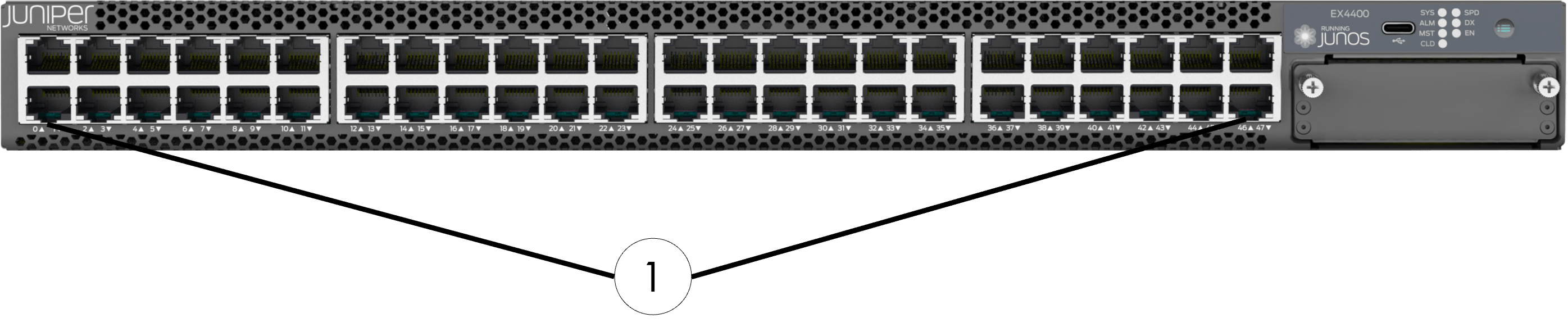
The EX-series switch provides a dedicated management network for all rack components. It is mounted at RU41.Management switch cabling is not user-accessible. The uplink port is exposed via a patch coupler labeled “AccSw MGMT Uplink” in the upper left rear of the rack.
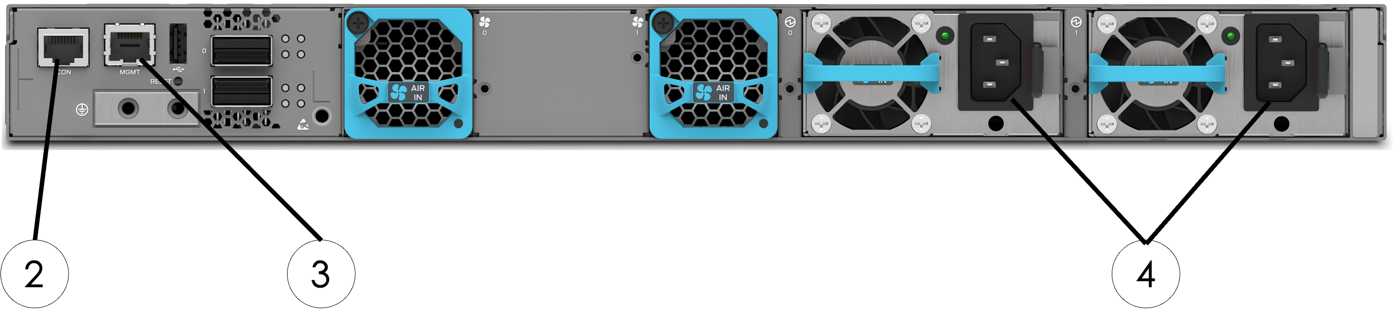
Port assignments – 2-PDU config (management switch)
The table below details the management switch connections to all rack components.Management switch cabling is configured at the factory. Do not modify unless directed by SambaNova support.
Serial console server (Lantronix) – 2-PDU config
The serial console server provides out-of-band CLI access to all rack components for troubleshooting and recovery. It is mounted at RU42.Serial console server cabling is not user-accessible. The network port is exposed via a patch coupler labeled “SCS NET UPLINK” in the upper left rear of the rack.
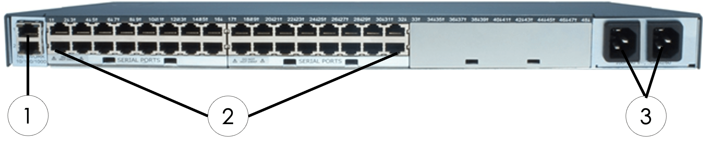
Port assignments – 2-PDU config (serial console server)
The table below details the serial console server connections to all rack components.Serial console server cabling is configured at the factory. Do not modify unless directed by SambaNova support.
Power distribution – 2-PDU config
PDU locations – 2-PDU config
Two PDUs provide redundant power for all rack components.Redundancy design – 2-PDU config
The power architecture protects against multiple failure scenarios:- Dual power supplies: Each component has two PSUs connected to different PDUs
- Redundant PDUs served by redundant power feeds
PDU cabling is configured at the factory. Do not modify unless directed by SambaNova support.
Power connections – 2-PDU config
The following table shows which PDU port powers each component. Each component’s dual PSUs connect to different PDUs within a redundant pair.Network and management components (PDUs 1 and 2) – 2-PDU config
Host module (PDUs 1 and 2) – 2-PDU config
XRDUs 0–7 (PDUs 1 and 2) – 2-PDU config
SambaRack SN40L-16 Rack components (4 PDU configuration)
This table lists the primary components included at the rack level. These components provide compute capacity, networking, management access, and redundant power for the SambaRack SN40L-16 system.SambaRack SN40L-16 Node components – 4-PDU config
This table details the components that make up a single SambaRack SN40L-16 node. These components deliver accelerator compute capability and support system management and monitoring.
All racks ship with components pre-mounted, internal cabling connected, and filler panels installed.
Rack layout – 4-PDU config
The figure below shows component locations from the rear of the rack. All cabling is performed at the rear.Component locations (rear view) – 4-PDU config
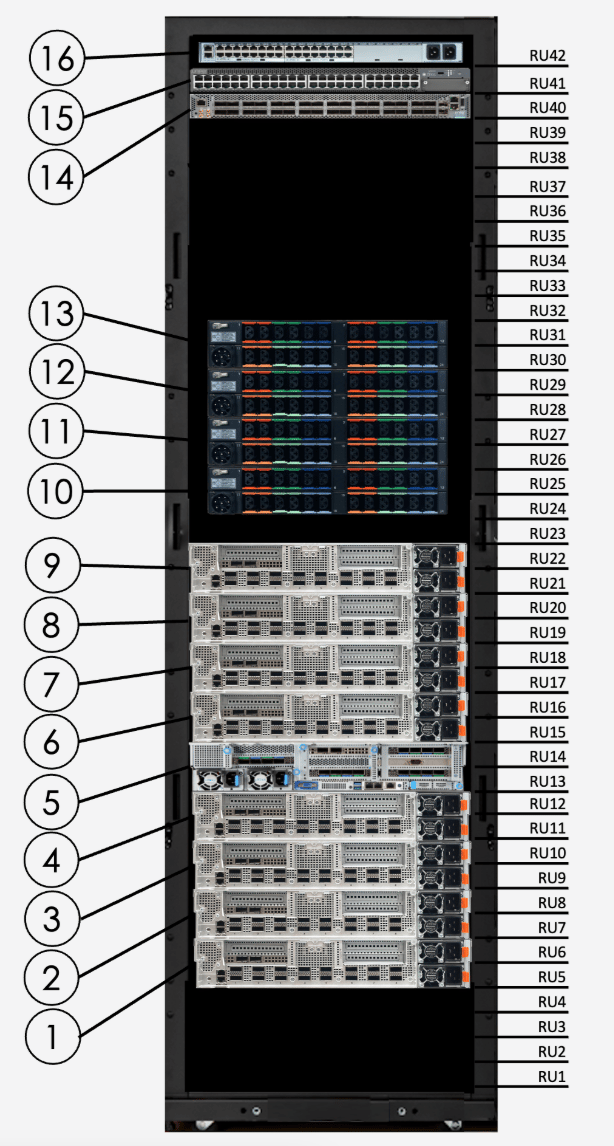
Compute components – 4-PDU config
SN40L-H host module – 4-PDU config
The host module manages accelerator operations and provides the primary interface to the rack’s compute resources.SN40L-2 XRDU module – 4-PDU config
Each XRDU module contains two RDUs and connects to both the management network and the high-bandwidth data network.Networking components – 4-PDU config
The rack includes three networking devices: a high-bandwidth data switch for inference traffic, a management switch for component administration, and a serial console server for out-of-band access.High-bandwidth data switch (Juniper QFX5130) – 4-PDU config
The QFX5130 provides 400GbE connectivity for all data path components. Connections to XRDUs and the host module use 400GbE to 2×200GbE DAC splitter cables, delivering 200GbE per endpoint.Port assignments – 4-PDU config (high-bandwidth switch)
The figures below show port assignments for the SN40L-H and SN40L-2 XRDUs. The table details all high-bandwidth data switch connections using 400GbE to 2×200GbE DAC splitter cables.High-bandwidth data switch cabling is configured at the factory. Do not modify unless directed by SambaNova support.
Management switch (Juniper EX-series) – 4-PDU config
The EX-series switch provides a dedicated management network for all rack components. It is mounted at RU41.Management switch cabling is not user-accessible. The uplink port is exposed via a patch coupler labeled “AccSw MGMT Uplink” in the upper left rear of the rack.
Port assignments – 4-PDU config (management switch)
The table below details the management switch connections to all rack components.Management switch cabling is configured at the factory. Do not modify unless directed by SambaNova support.
Serial console server (Lantronix) – 4-PDU config
The serial console server provides out-of-band CLI access to all rack components for troubleshooting and recovery. It is mounted at RU42.Serial console server cabling is not user-accessible. The network port is exposed via a patch coupler labeled “SCS NET UPLINK” in the upper left rear of the rack.
Port assignments – 4-PDU config (serial console server)
The table below details the serial console server connections to all rack components.Serial console server cabling is configured at the factory. Do not modify unless directed by SambaNova support.
Power distribution – 4-PDU config
PDU locations – 4-PDU config
Four PDUs provide redundant power for all rack components.Redundancy design – 4-PDU config
The power architecture protects against multiple failure scenarios:- Dual power supplies: Each component has two PSUs connected to different PDUs
- Redundant PDU pairs: PDUs 1 and 2 form one pair; PDUs 3 and 4 form another
- Cross-pair distribution: XRDUs 0–3 and the host use PDUs 1/2; XRDUs 4–7 use PDUs 3/4
PDU cabling is configured at the factory. Do not modify unless directed by SambaNova support.